


Page 18
LAARS HEATING SYSTEMS
d’obstruction, d’étranglement, de fuite, de
corrosion et autres défaillances qui pourraient
présenter des risques.
3. Dans la mesure du possible, fermer toutes les
portes et les fenêtres du bâtiment et toutes les
portes entre l’espace, où les appareils tojours
raccordés et les autres espaces du bâtiment.
Mettre en marche les sécheuses, tous les
appareils non raccordés au système d’évacuation
commun et tous les ventilateurs d’extraction
comme les hottes de cuisinère et les ventilateurs
des salles de bain. S’assurer que ces ventilateurs
fonctionnent à la vitesse maximale, Ne pas faire
fonctionner les ventilateurs d’été. Fermer les
registres des cheminées.
4. Mettre l’appareil inspecté en marche. Suivre les
instructions d’allumage. Régler le thermostat de
façon continue.
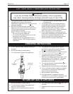
5. Faire fonctionner le brûleur principal pendant 5
min ensuite déterminer si le coupe-tirage
déborde à l’ouverture de décharge. Utiliser la
flamme d’une allumette ou d’une chandelle ou la
afumée d’une cigarette, d’une cigare ou d’une
pipe.
6. Une fois qu’il a été déterminé, selon la méthode
indiquée ci-dessus, que chaque appareil raccordé
au systéme d’évacuation est mis à l’air libre de
façon adéquate. Remettre les portes et les
fenêres, les ventilateurs, les registres de
cheminées et les appareils au gaz à leur position
originale.
7. Tout mauvais fonctionnement du systéme
d’évacuation commun devrait êvacuation
commun devrait être corrigé de façon que
l’installation soit conforme au National Fuel
Gas Code, ANSI Z223.1/NFPA 54 et (ou) aux
codes d’installation CAN/CGA-B149. Si la
grosseur d’une section du systéme devrait être
modifié ppour respecter les valeurs minimales
des tableaux pertinents de l’appendice F du
National Fuel Gas Code, ANSI Z223.1/NFPA 54
et (ou) des codes d’installation CAN/CGA-B149.
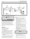
6B. Filling the System
1. Open all supply and return valves.
2. Fill heating system to minimum operating
pressure 12 psig.
3. Loosen screw in coin vent and allow any trapped
air to escape. Collect any water that escapes so
that it does not drip on the blower electronics and
damage them. Small amounts of air that may
remain will be purged by the internal pump.
Tighten screw after purging.
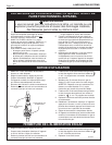
*The “manual operation” lever located on the
side of the valve operator requires moderate pressure
to latch the valve open and then again to unlatch it and
allow it to close.
4. Purge all lines by opening vents.
5. Close gas shutoff valve located above gas valve.
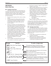
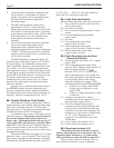
6. Turn on 120 volt power, the display will initially
display [
---
] for five seconds before displaying
[OFF].
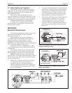
7. If the temperature sensor detects a temperature
below 39°F (4°C) it will display [ICE]. The
appliance will then be in the frost protection
mode. The pump initially runs alone for 5 minutes
or until the flow temperature reaches 45°F (7°C).
(EBP ONLY: When the internal zone valve is
manually* opened the water will be pumped to
the space heating.) This is a good time to ensure
that the system is fully discharged of all air and
the water charge pressure is correct. Should the
water temperature remain below 45°F (7°C) after
5 minutes the appliance will start the ignition
sequence. After three attempts to ignite the
burner control will lock out and display [LO]
(see Figure 25).
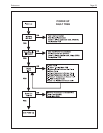
8. If the display remains at [OFF], press the on/off
button on the front panel and the reset button on
top of the front panel. The pump and the blower
will start, the display will then flash [
] (boiler
flow temperature) for 1 second intervals and the
actual temperature (e.g., [127]) in degrees F for
3 second intervals. The appliance will attempt to
ignite three times after which it will lock out and
display [LO]. The fan and the pump will then
stop. Ensure that the system is fully discharged
of all air and the water charge pressure is correct.
9. Turn the main electrical supply off.
10. EBP ONLY: Manually reset the internal zone
valve to its normal position (manual level
toward top of actuator).
11. System is now ready for operation.
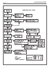
6C. Firing Burner
1. Be sure that system has been filled properly and
is leak tight.
2. Open gas shutoff valve.
3. Turn on main electrical switch.
4. If the temperature sensor detects a temperature
below 39°F (4°C) it will display [ICE]. The
appliance will then be in the frost protection
mode.
5. If the display remains at [OFF], press the on/off
button on the front of the control panel and the
reset button on top of the control panel.
6. The pump and the blower will start, the display
will show [
] (boiler flow temperature) for
1 second intervals and the actual temperature
(e.g., [127]) in degrees F for 3 second intervals.