


Endurance
Page 21
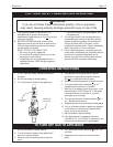
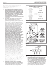
jacket, remove the four (4) long screws that secure the
top and bottom pans. Remove the air vent and the top
pan. Remove the insulation retainer and the coil cover
insulation. Clean the boiler coil with a wire brush and
vacuum debris from the combustion chamber (avoid
hitting the ignitor or the flame sensor with the brush
or vacuum hose because they are fragile).
After cleaning, assemble the parts in the reverse
order, open isolation valves and bleed air from the
boiler and the system. Follow the lighting instructions
and start the boiler. Check operation.
SECTION 8
Servicing.
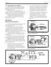
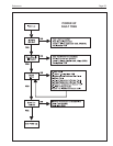
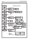
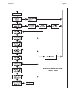
8A. Sequence of Operation
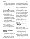
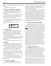
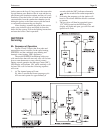
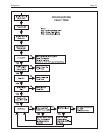
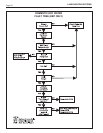
Figures 22 and 23 depict the flow paths and
temperature sensor locations for the space heating,
EDP/EDN, and the combined space heating and
domestic water heating, EBP, appliances.
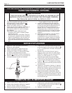
The model EDP/EDN modulating boilers are
cold start boilers that will start only on a call for heat
from a room thermostat or zone control contact.
During normal operation the Message Center [MC]
LED display will indicate ‘ON’ while awaiting a call
for heat. On a call for heat the following sequence
will occur.
1. (a) The internal pump will start.
(b) After 5 seconds the blower prepurge cycle
will start and operate for approximately 6
seconds while the [MC] indicates alternately
and the current boiler outlet temperature.
2. Following the prepurge cycle the ignitor will
heat for 10 seconds while the blower continues
to operate.
3. The gas valve will then be energized (green
‘GV’ LED located on the PCB next to the
display will light) and open, gas will flow and
ignition will occur.
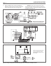
Figure 28. EBP Flow Schematic.
Figure 27. EDP/EDN Flow Schematic.