


Page 20
LAARS HEATING SYSTEMS
storage vessel to reduce boiler cycling on small output
heating zones and to provide additional heat for
domestic hot water through the domestic hot water
(DHW) plate heat exchanger.
If a tank change is necessary, access to the tank
is possible by removing the jacket’s lower front panel.
This is done by removing the screws that hold the
panel at the top and lifting the panel away. Isolate the
appliance and drain down using the drain cock at the
base of the tank. Remove the tank sensor. Undo the
union and the pump flange bolts that connect the tank
to the boiler, unscrew the panel between the upper and
lower compartments, support the upper components
and remove the tank. Installation of the new tank is
done in the reverse order. After installation purge all
air from the boiler before restarting.
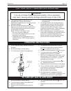
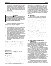
7I. Thermostatic Union (EDP/EDN)
The thermostatic union is a 1¼" NPTF union
which must be mounted at the flow outlet to control
boiler temperature. The union must be installed so that
union nut is on the boiler side of the connection. This
insures that the thermostat is properly positioned with
its spring facing up, toward the system. The element
has two small bypass holes that allow some water to
flow into the system at all times. When the boiler first
starts and the element is closed, boiler water is re-
circulated back to the return until the supply water
reaches 160°F (71°C). The element then modulates
open. If the temperature does not exceed 150°F (66°C)
within two minutes after firing, the element is not
functioning properly. To replace the element, shut off
and drain the section of the system adjacent to the
thermostatic union. Open the union and replace the
element with a new one. The element should be
installed so that its spring and actuator are facing the
system side (up). Close the union, open the valves,
refill and bleed the system. Ensure that air is venting
from the air vent on top of the boiler chamber and it is
left operational. Restart boiler.
7J. Cleaning the Boiler Coil
The Endurance is equipped with a premixed
combustion system. This type of combustion system
does not create free carbon (soot) except in very rare
instances and therefor the combustion chamber coil
will probably never need cleaning. If cleaning is
required, proceed as follows: valve off the boiler,
switch off the electrical power at the disconnect
switch, drain 1-2 gallons (4-8L) of water from the
boiler drain, remove the flue assembly from the top of
the boiler, remove the pump flange bolts from the top
pump flange, disconnect the sensor wires from the
sensors (boiler flow, return and safety limit), undo the
union nut from the boiler flow manifold, and remove
the four (4) screws from the bottom gas valve flange.
The boiler assembly may now be removed from the
jacket. After removal of the boiler assembly from the
Replace in reverse order ensuring that the connections
are correct.
*EBP combination units only.
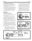
7E. Ignitor / Flame Sensor Assembly
The ignitor is a “glow bar” type ceramic
composite device. It is energized whenever there is a
call for heat and switched off when ignition is
established.
The flame sensor is a remote sensing flame rod
which is connected directly to the circuit board “J5”
terminal. The ignitor should read 50 to 100 ohms
resistance when at room temperature.
If the ignitor fails and the assembly must be
replaced, always install a new ignitor gasket with the
replacement assembly.
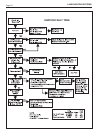
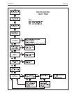
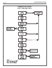
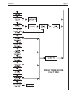
For sequence of operation, see Section 8,
Servicing.
Caution
Ignitor gets hot.
7F. Transformer
The control transformer accepts 120 VAC line
voltage and provides 80 VA of 24 VAC control
voltage for the boiler control ONLY. It is NOT
capable of supplying control voltage for external
devices such as zone valves, which MUST have their
own separate power supply.
Should the transformer require replacing, shut off
the 120 volt power. Unplug the transformer wires from
the PCB, unscrew the two fixing screws and remove
the transformer.
Fit the replacement transformer in reverse order.
7G. Blower
The combustion air blower is a high pressure
centrifugal blower. It is powered by a 24VDC motor
which is controlled by the PCB. Its speed will be
varied according to the temperature of the boiler flow.
If a blower change is required, turn off the 120
volt power and unplug the wires from the blower
motor. Remove the four nuts from the blower
discharge flange and the four screws that secure the
gas manifold to the gas valve. Remove the complete
assembly. Unscrew the combustion air inlet assembly
and register plate from the fan.
Fit the replacement fan in reverse order, ensuring
that all joints are made correctly and sealed.
After replacement the combustion should be
checked for correct air fuel ratio (see Check, Test and
Start-Up section).
7H. Transfer Tank (EBP)
The transfer tank contains approximately 20
gallons of boiler water. It functions as an energy