


Endurance
Page 17
the flame of a match or candle, or smoke from a
cigarette, cigar or pipe.
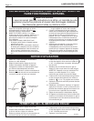
6. After it has been determined that each appliance
remaining connected to the common venting
system properly vents, when tested as outlined
above, return doors, windows, exhaust fans,
fireplace dampers and any other gas burning
appliance to their previous conditions of use.
7. Any improper operation of the common venting
system should be corrected so the installation
conforms with the
a. National Fuel Gas Code, ANSI Z223.1
latest edition.
b. Can / CGA - B149.
When re-sizing any portion of the common
venting system, the common venting system should be
re-sized to approach the minimum size as determined
using the appropriate tables in Appendix F in the
National Fuel Gas code, ANSI Z223.1 - latest edition,
and/or Can/CSA B149 Installation Codes.
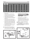
6A. Common Vent Test
Au moment du retrait d’une chaudière existante,
les mesures suivantes doivent être prises pour chaque
appareil toujours raccordé au système d’evacuation
commun et qui fonctionne alors que d’autres appareils
toujours raccordés au système d’évacuation ne
fonctionnent pas:
1. Sceller toutes les ouvertures non utilisées du
système d’évacuation.
2. Inspecter de façon visuelle le système
d’évacuation pour déterminer la grosseur et
l’inclinaison horiztonale qui conviennent et
s’assurer que le système est exempt
SECTION 6.
Boiler Start Up
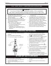
6A. Common Vent Test
At the time of removal of an existing boiler, the
following steps shall be followed with each appliance
remaining connected to the common venting system
placed in operation, while the other appliances
remaining connected to the common venting system
are not in operation.
1. Seal any unused opening in the common venting
system.
2. Visually inspect the venting system for proper
size and horizontal pitch and determine there is
no blockage or restriction, leakage, corrosion
and other deficiencies which could cause an
unsafe condition.
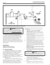
3. Insofar as is practical, close all building doors
and windows and all doors between the space in
which the appliances remaining connected to the
common venting system are located and other
spaces of the building. Turn on clothes dryers
and any appliance not connected to the common
venting system. Turn on any exhaust fans, such
as range hoods and bathroom exhausts, so they
will operate at maximum speed. Do not operate a
summer exhaust fan. Close fireplace dampers.
4. Place in operation the appliance being inspected.
Follow the lighting instructions. Adjust
thermostat so appliance will operate
continuously.
5. Test for spillage at the draft hood relief opening
after 5 minutes of main burner operation. Use
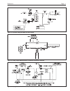
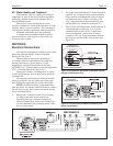
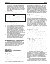
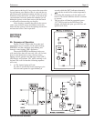
Identifies
Boiler Flow Temp (Supply)
Tank Temp
Return Temp (Boiler Inlet)
On
Off
Lock Out - Combustion Related
Fault Code (Three) There are 8
different Fault Codes defined.
Freeze Protection
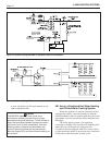
To read or change mode
During operation display will default to supply
temperature. Press temperatures button repetitively.
To sequence through three temperature indicators.
Boiler in standby mode: will operate on call for domestic
water or heat zone demand.
Boiler switched OFF. Press ON/OFF button for “ON”.
After three trials for ignition, will stand in lockout. Press
reset on top of panel to retry.
A fault code may be indicated on the display prior to pushing
the reset button or switching the on-off button or power
switch. Observe code, and note it, for servicing.
Sensor has detected return temperature below 39°F (4°C).
Figure 26. Typical Display Identification Codes.
Message