Serial Communication, cont’d
PVS 204SA • Serial Communication
4-6
PRELIMINARY
Volume adjustment
Set the overall output volume X^ V Vol X^ ] Specify the volume (0-100) for
the audio output.
Example: 27V Vol027 ] Set volume to 27.
Increment the volume +V Vol X^ ] Increase audio output.
Decrement the volume -V Vol X^ ] Decrease audio output.
View the volume level V Vol X^ ] Show the output volume.
Status commands
These commands allow you to view the status of the clip indicator between adjustments to the audio input levels, the
Volume Control Module status, the high pass lter status, and the internal temperature of the device.
View the clip (max) status 3S Sts3*X# ]
View the VCM present status 40S Sts40*X1# ]
View the high pass lter status 41S Sts41*X# ]
View the internal temperature (ºC) 20S Sts20*X1$ ]
Front panel security lockout modes (executive modes)
Disable executive mode (unlock) 0X Exe X# ] Adjustments and selections can
be made from the front panel.
Enable executive mode 1 (lock) 1X Exe X# ] Lock front panel input selection
buttons; select inputs via RS-232
or IR remote control only. Only
volume adjustment is available
via the front panel.
This command is equivalent
to pressing and holding front
panel buttons 1 and 4.
View the executive mode status X Exe X# ] Show executive mode status.
Example: X Exe0 ] Executive mode is off
(unlocked).
Firmware version, part number & information requests
Query firmware version number Q X2! ] Show the switcher’s firmware
version.
Request the part number N N60-800-01 ] Show the switcher’s part #.
Request model name 1I PVS 204SA ]
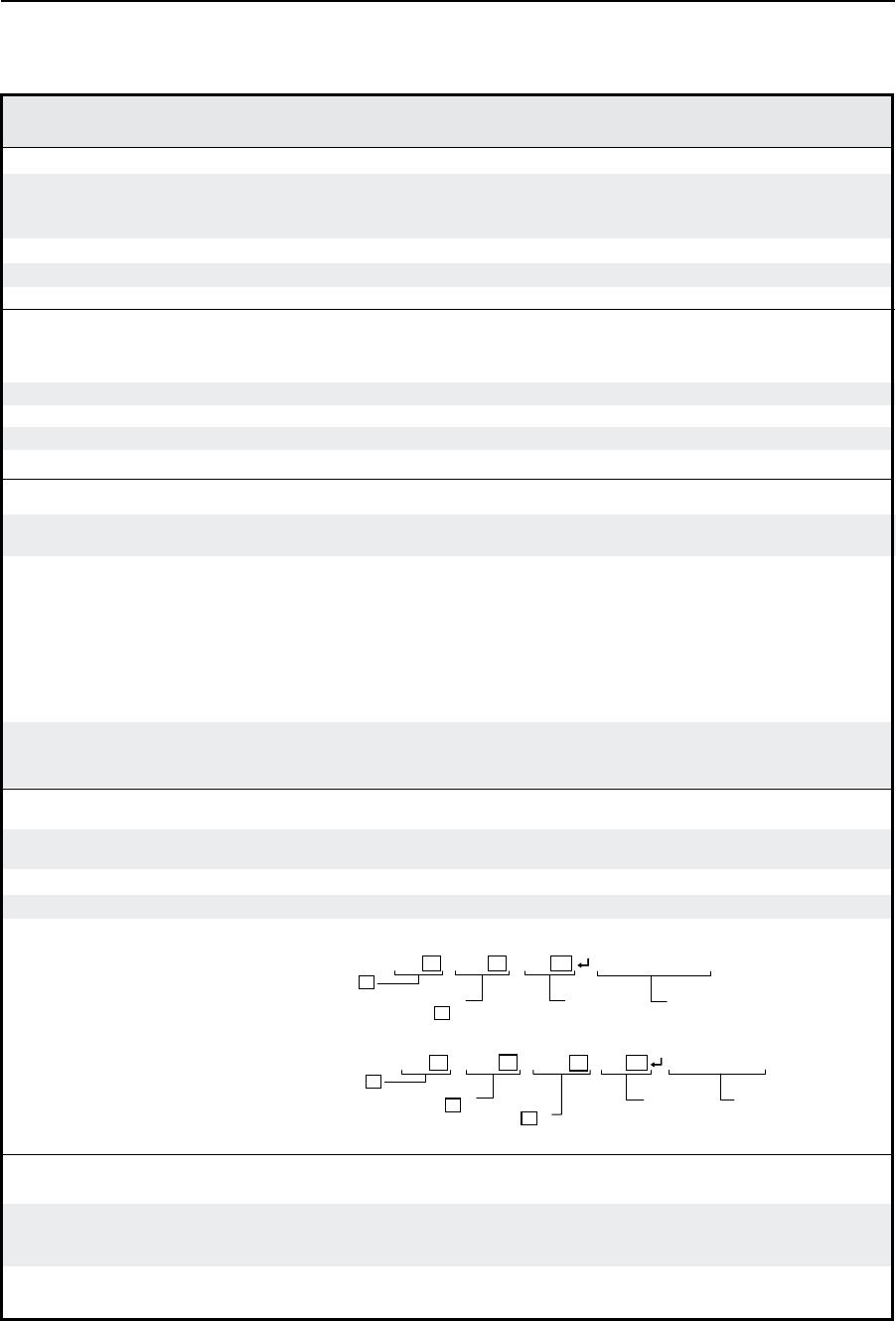
Request general info I or 0I (see below ) Show the switcher’s status.
Vid • Aud • Vol
X1 X1
X6
Video input # X1
is selected/active
Audio input
# X1 is
selected/active
Audio volume
status
(Single sw mode)
Switcher mode
status
Vga • Vid
*
• Aud
*
• Vol
(Sep sw mode)
X1
X1
X4
X1
RGB input # X1
is selected/active
Video input
# X1 is
selected/active
Audio volume
status
Audio input
# X1 is
selected/active
Switcher mode
status
Upload rmware
Upload E Upload ] Go ] The switcher will start upload-
ing firmware code into its
memory.
Upl ] The firmware was successfully
loaded into the switcher.
Command/response table for SIS commands (continued)
Command ASCII Command Response Additional description
(host to switcher) (switcher to host)
(separate switcher mode)
(single switcher mode)


