Commander GP User Guide
Issue code: gpxu2
D-16 Menu 0 Parameters
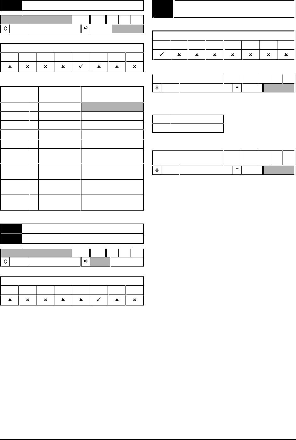
0.26 Analog input 2 mode selector
RW Txt P
(See below) VOLt
Applicable to Macros...
01234567
Set the required mode as follows:
Setting Input signal When current
signal ≤≤3mA...
VOLt 0 0V to 10V
0–20 1 0 to 20mA Signal treated as zero
20–0 2 20mA to 0 Signal treated as zero
4–20.tr 3 4mA to 20mA Drive trips
20–4.tr 4 20mA to 4mA Drive trips
4–20.Lo 5 4mA to 20mA Drive runs at minimum
or low speed
20–4.Lo 6 20mA to 4mA Drive runs at minimum
or low speed
4–20.Pr 7 4mA to 20mA Drive runs at previous
speed
20–4.Pr 8 20mA to 4mA Drive runs at previous
speed
0.26 Post-scaling PID reference
0.27 Post-scaling PID feedback
RO Bi
±1000
Hz
Applicable to Macros...
01234567
These parameters are used for monitoring the PID
reference and PID feedback. Refer to Macro 5 in
Chapter 3 Setting Up the Drive.
0.27 EUR> Positive logic select
USA> Sequencing mode selector
Applicable to Macros...
0123
567
European configuration
Positive logic select
RW Bit R P
0 ~ 1 0
Use 0.27 to select the logic polarity of the digital
inputs, as follows:
0 Negative logic
1 Positive logic
USA configuration
Sequencing mode
selector
RW Uni P
0 ~ 4 4
Use 0.27 to change the functions of the digital
inputs; these functions determine the digital control
mode.
The default setting (4) gives the functions shown in
the signal connection diagrams in Chapter 3 Setting
up the Drive.
Set 0.27 at 0 for digital control by momentary
contacts. See Macro 0 in Chapter 3 Setting up the
Drive.
It is essential that you see 0.29 USA> Terminal-29
destination selector in order to set up a RUN PERMIT /
STOP input.
For other settings of 0.27, see the Commander Gp
Advanced User Guide.


