Commander GP User Guide
Issue code: gpxu2
D-4 Menu 0 Parameters
Voltage boost
0.07 Voltage mode selector
Voltage mode selector
RW Uni
(See below) Ur_I
Setting Function
Vector modes
Ur_S
0 Motor stator resistance is measured each
time the Drive is started.
Ur_I
1 Motor stator resistance is measured at
power-up if the
EXTERNAL TRIPEXTERNAL TRIP contact is
closed and no other trip condition exists.
Ur
2 Motor stator resistance is not measured
(use this mode only after having used
Ur_S or Ur_I to measure the stator
resistance).
Fixed boost mode
Fd
3 Fixed voltage boost that can be manually
adjusted by parameter 0.08 Boost voltage.
Use 0.07 to select fixed voltage boost, or Vector
control of voltage boost. Fixed boost requires a
value to be set in 0.08 Boost voltage by the user.
See Figure D–1. Fixed boost should be used when
0.39 Synchronize to a spinning motor is set at 1.
Motor voltage
[0.08]
Voltage boost
Frequency
Figure D–1 Effect of fixed voltage boost on
the voltage-to-frequency
characteristic
Vector control causes the voltage boost to be
automatically regulated according to the load on
the motor.
Vector control requires the value of stator winding
resistance to be stored in a parameter in the Drive.
The three Vector modes allow the resistance to be
measured under different circumstances.
0.08 Boost voltage
Boost voltage
RW Uni
0 ~ 25.0 3.0 % x [0.44]
When 0.07 Voltage mode selector is set at Fd, set
0.08 at the required value for the motor to run
reliably at low speeds. See Figure D–1.
Excessive values of 0.08 can cause the motor to be
overheated.
0.09 Dynamic V/f select
Dynamic V/f select
RW Bit
0 ~ 1 0
Set 0.09 at 0 when the V/f characteristic applied to
the motor is to be fixed. It is then based on the
rated voltage and frequency of the motor.
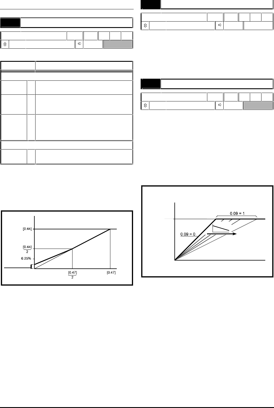
Set 0.09 at 1 when reduced power dissipation is
required in the motor when it is lightly loaded. The
V/f characteristic is then variable resulting in the
motor voltage being proportionally reduced for
lower motor currents. Figure D–2 shows the change
in V/f slope when the motor current is reduced.
Motor
voltage
Frequency
AC supply
voltage
IMOTOR
Figure D–2 Fixed and variable
V/f characteristics


