Commander GP User Guide
Issue code: gpxu2
2-2 Getting Started
111
21 31
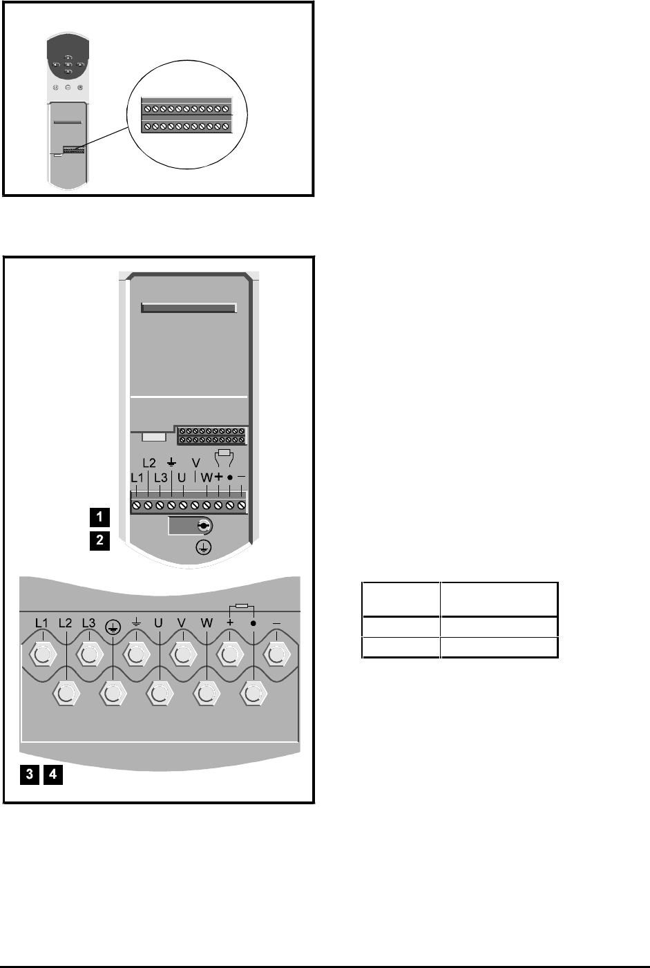
Figure 2–2 Location of the signal connector
Figure 2–3 Locations of the power connectors
1. Observe the safety warnings and cautions given
in Chapter 1 Safety information of the Installation
Guide and in this chapter.
2. Refer to the following:
• Chapter 2 of the Installation Guide in order
to install the Drive
• Figure 2–2 for the location of the
signal connector
• Figure 2–3 for the locations of the
power connections
• Figure 2–5 or 2–6 in this chapter in order to
make the signal and power connections for
operation in Terminal or Keypad mode.
Note that Macros 2, 3, 4, 5, 6 operate only in
Terminal mode. If one of these macro
configurations is to be enabled after the
initial setting up covered in this chapter, you
may wish to set up the Drive now in
Terminal mode in order to learn how to
operate it in this mode.
Signal connector for all models The two
terminal blocks of the signal connector can be
unplugged from the Drive by pulling them
downward.
Power connector for model sizes 1
and 2 The power connector can be unplugged
from the Drive by pulling it downward.
Power connections to model sizes 3
and 4 The power connections are made to
M10 studs located in the power section of the
Drive.
3. Note that the default user-interface mode is
as follows:
Continent User-interface
mode
EUR Terminal
USA Keypad
(Instructions for changing the user-interface
mode are given later.)


