


9
Installation and Set-Up
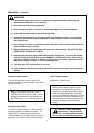
Receiving And Handling
After the machine has been uncrated, examine the
case sealer for damage that might have occurred
during transit. If damage is evident, file a damage
claim immediately with the transportation company
and also notify your 3M Representative.
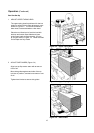
PACKAGING AND SEPARATE PARTS
1. Lift fiberboard cover off pallet after removing
staples at bottom.
2. Remove protective wrapping around machine.
3. Remove hardware that secures case sealer legs
to pallet.
4. Cut and remove cable tie that secures black
electrical conduit to the electrical mast on top of
machine.
Machine Set-Up
Important Read "Warnings", on page
14, before attempting to set-up the case
sealer for operation.
Note A tool kit consisting of metric open
end and hex socket wrenches is provided
with the machine. These tools should be
adequate to set-up the machine, however,
other tools supplied by the customer will be
required for machine maintenance.
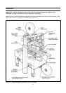
The following instructions are presented in the order
recommended for setting up and installing the case
sealer, as well as for learning the operating
functions and adjustments. Following them step
by step will result in your thorough understanding of
the machine and an installation in your production
line that best utilizes the many features built into the
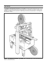
case sealer. Refer to Figure 3-1 to identify the
various components of the case sealer.
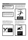
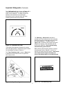
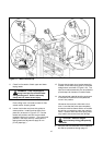
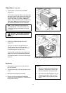
WARNING Follow this step
carefully as spring pressure is
applied to applying and buffing arms when
cable tie is removed. Keep hands/fingers
AWAY from tape cut-off knife under orange
knife guard. Knife is extremely sharp and
can cause severe injury.
Hold taping head BUFFING ROLLER and cut
and remove cable tie that holds applying/buffing
arms retracted. See Figure 2-1C. Allow buffing/
applying arms to extend slowly.
5. Cut cable ties that secure upper assembly to
machine bed on each side of machine. Remove
and discard cable ties and protective foam
sheeting.
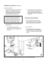
6. Remove tape drum bracket bolts (4) from top
crossbar and install tape drum bracket from
parts box on top crossbar as shown in
Figure 2-1A.
7. Install height adjustment crank handle on top of
left column as shown in Figure 2-1B. Crank
upper assembly up high enough to allow clear
access to lower taping head. Remove and
discard the two cushion shipping blocks.
8. Loosen both side guides, pivot to full open
position and re-tighten locking knobs.
9. Wipe protective shipping oil off stainless steel
covers on machine bed.
10. Cut and remove cable ties on both upper and
lower taping heads. (Applying/buffing rollers are
held retracted for shipment.)