


10
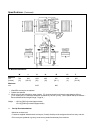
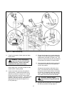
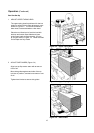
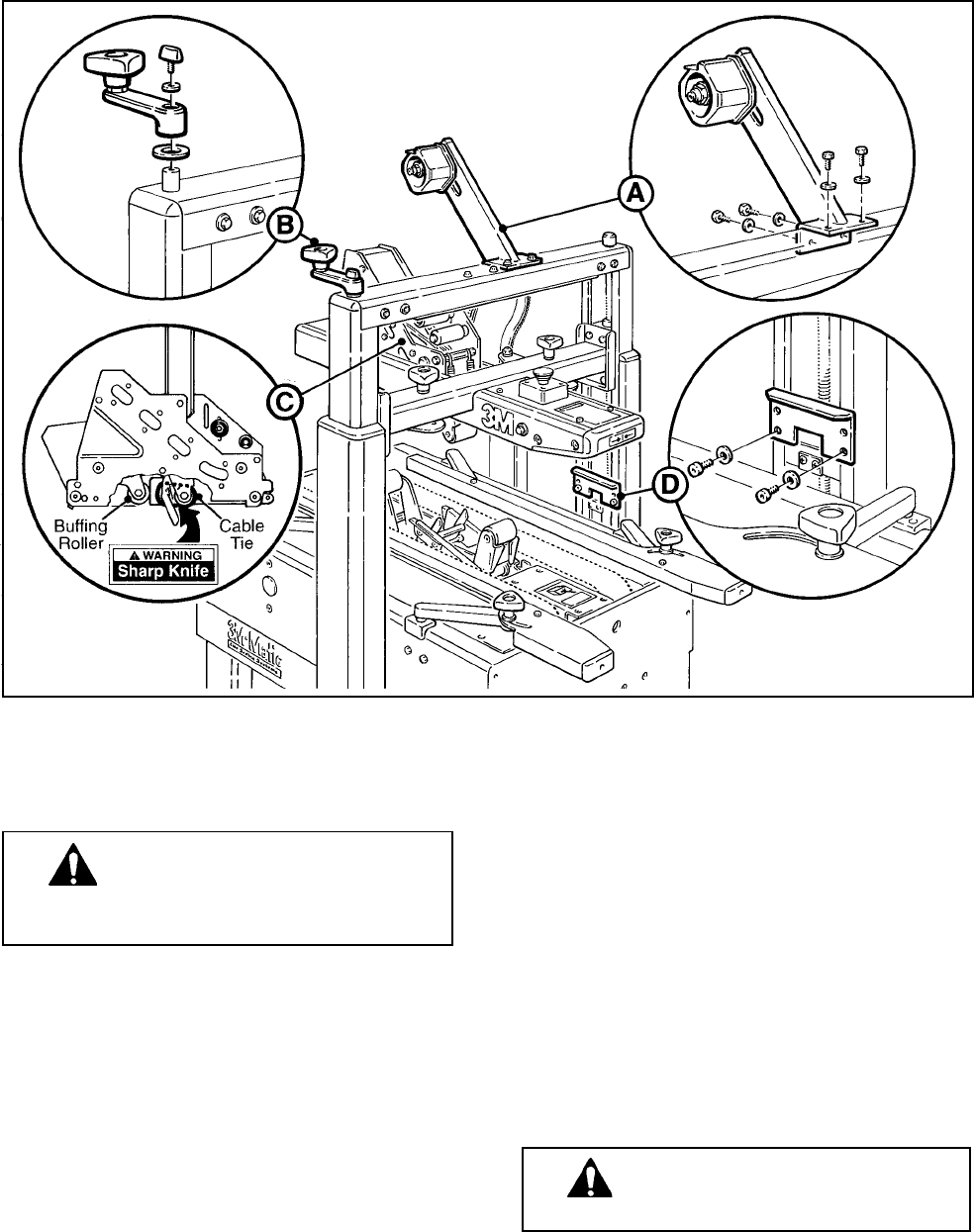
Figure 2-1 200a Frame Set-Up
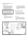
11. Check for free action of both upper and lower
taping heads.
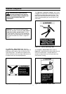
WARNING Keep hands/fingers
away from tape cut-off knife under
orange knife guard. Knife is extremely
sharp and can cause severe injury.
Push buffing roller into head to check for free,
smooth action of taping heads.
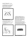
12. Loosen lock knobs and pivot side guides to
center position. Install machine stops (from
parts box) as shown in Figure 2-1D. Use the
lowest hole position and bolt into the lowest
threaded insert on the column. (The upper hole
position in the stops are only used when the
taping heads are adjusted to apply 50 mm
[2 inch] tape legs.)
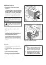
13. Ensure that the tape drum bracket assembly,
located on the lower taping head, is mounted
straight down, as shown in Figure 2-2A. The
tape drum bracket assembly can be pivoted to
provide tape roll clearance in certain cases.
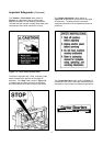
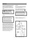
14. Use appropriate material handling equipment
to remove the machine from the pallet and
move it into position.
Whenever the machine is lifted with a fork
truck, insure that the forks span completely
across the machine frame and do not contact
any wiring or mechanism under the machine
frame. In some cases the lower taping head
may need to be removed to avoid damage.
15. Continue with the remainder of the Installation
and Set-Up procedure through page 12.
CAUTION Machine weighs
approximately 123 kg [280 pounds]
uncrated.