


24
Special Set-Up Procedure (Continued)
WARNING Turn off electrical power and disconnect power cord from electrical supply
before beginning Special Set-Up Procedure. If power cord is not disconnected, severe injury
to personnel could result.
TAPING HEADS
WARNING Use care when working near knives as knives are extremely sharp. If care is not
taken, severe injury to personnel could result.
CAUTION Taping head weighs approximately 7.2 kg [16 lbs]. Use proper body
mechanics when lifting upper or lower taping heads.
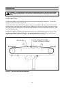
4. Install and tighten the six screws and plain washers in each column that were removed in Step 2. Crank
upper taping head assembly up and remove blocks.
If desired, the bed height can now be decreased to 520 mm [20.5 inch] by adjusting legs upward. (See
"Installation and Set-Up Machine Bed Height", Page 11.)
WARNING Blocks and spacers must be capable of supporting the 34 Kg [75 pound] weight
of the outer columns and upper taping head assembly.
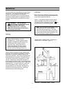
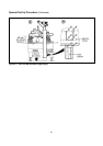
Box and Machine Bed Height Range Refer to Figure 6-2
Moving the outer columns up one set of mounting holed increases the maximum box size handled by the
200a case sealer and decreases the minimum machine bed height.
Note This also increases the minimum box height from 120 mm [4.75 inch] to 165 mm [6.5 inch].
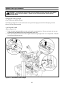
To move the outer columns up one set of mounting holes:
1. Place minimum 305 mm [12 inch] high blocks at the front and rear of the upper taping head assembly as
shown in Figure 6-2A. Important Blocks (front and rear) must be same height in order to keep upper
taping head assembly parallel with machine bed/drive belts. Crank the upper taping head assembly
down until it touches these blocks.
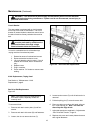
2. Remove and retain the six screws and plain washers that fasten each column to the frame. Figure 6-2B.
3. Turn the height adjustment crank clockwise to raise the outer columns up one set of mounting holes
(100 mm [4 inch]).
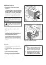
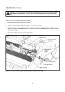
1. Loosen, but do not remove, the two retaining screws that secure the upper taping head shown in
Figure 6-1B.
2. Slide the head forward and lift straight up to remove it from the case sealer.
3. Lift the lower taping head, shown in Figure 6-1C, straight up to remove it from the case sealer bed.
4. Refer to Section II, "Adjustments Changing Tape Leg Length", page 13 for taping head set-up.