


15
Adjustments (continued)
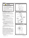
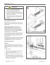
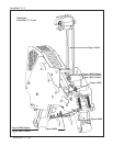
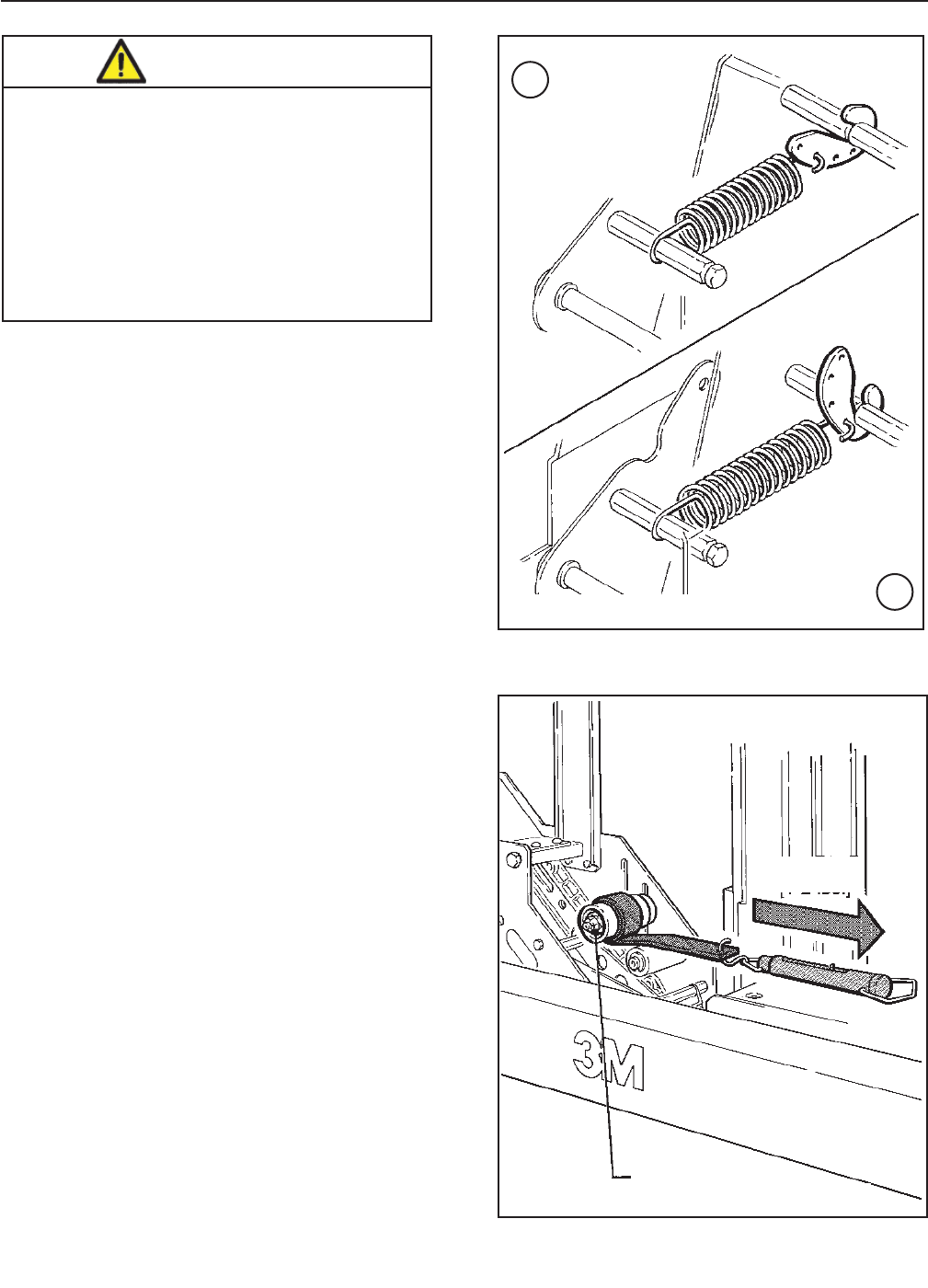
Applying Mechanism Spring
To obtain access to the spring, remove the taping
head cover (four mounting screws). Replace cover
when fi nished.
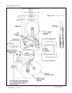
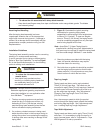
The applying mechanism spring, shown in
Figures 5-4A and 5-4B, controls applying and
buffi ng roller pressure on the box and returns
the mechanism to the reset position. The spring
pressure is pre-set, as shown in Figure 5-4A for
normal operation, but is adjustable.
If a tape gap appears on the trailing surface of the
box increase spring pressure. If the front of the box
is being crushed by the applying roller decrease
spring pressure.
Removing the spring end loop from the spring holder
and placing loop in other holes provided, as shown
in Figure 5-4B, will adjust the spring pressure.
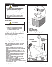
To Adjust Tension:
1. Wrap a cord or small strap (non-adhesive) 4-6
turns around the tension roller.
2. Attach a spring scale to the end of the cord or
strap.
3. Turn the adjusting nut with the socket wrench
provided, until a force of approximately 0.5 kg to
0.9 kg [1 to 2 lbs.] is required to turn the roller by
pulling on the spring scale.
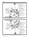
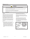
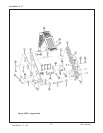
One-Way Tension Roller
Figure 5-5
The one-way tension roller is factory set. When
replacing this assembly, the roller must have a force
of approximately 0.5 kg to 0.9 kg [1 to 2 lbs.] when
turning.
AccuGlide 3 - 3" - NA
2012 January
Figure 5-4 – Applying Mechanism Spring
Figure 5-5 – One-Way Tension Roller
0.5 - 0.9kg
[1 - 2 lbs.]
Adjusting Nut
A
B
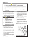
• To reduce the risk associated with shear,
pinch, and entanglement hazards:
− Turn air and electrical supplies off on
associated equipment before performing any
adjustments, maintenance, or servicing the
machine or taping heads
− Never attempt to work on the taping head
or load tape while the box drive system is
running
WARNING