29
13.10 Drive Belt Tension
Tension adjustment of the drive belts may be required during normal operation. Belt tension must be adequate to
positively move the box through the machine and they should run fully on the surface of the pulleys at each end of
the frame. The idler pulleys on the infeed end are adjusted in or out to provide proper belt tension. Each belt is
adjusted separately.
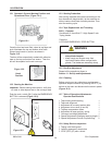
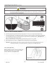
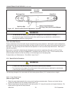
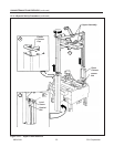
Belt tension is obtained by tightening the adjustment screw so that a moderate pulling force of 3.5 kg [7 lbs]
applied at the mid span, as shown in Figure 13-7, will defl ect the belt 25mm [1 inch]. This will assure positive
contact between the belt and the drive pulley on the discharge end of the taping head.
To adjust belts, see "Maintenance – Drive Belts", steps 3 and 7.
• To reduce the risk associated with pinch, entanglement and hazardous voltage:
− Turn electrical supply off and disconnect before performing any adjustments, maintenance or
servicing the machine or taping heads
WARNING
WARNING
13-MAINTENANCE AND REPAIRS (continued)
Figure 13-7 – Box Drive Belt Tension Adjustment, Top View
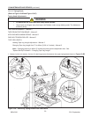
13.11 Special Set-Up Procedure
The following changes to the case sealer will allow taping boxes 90mm [3-1/2 inches] minimum height.
• To reduce the risk associated with mechanical and electrical hazards:
− Turn electrical and air supply off and disconnect before performing any adjustments, maintenance,
or servicing the machine or taping heads
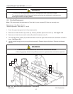
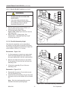
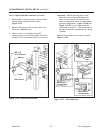
1. Raise the upper head assembly (by turning crank handle counterclockwise). Remove and retain the two
screws and washers from the normal position holes "A-A".
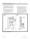
2. Remount and secure the stop bracket in the lower position "A" using the top holes and original fasteners. Re-
locate both the right and left stop brackets.
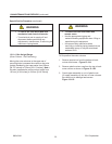
13.11.1 Case Sealer Frame
(Refer to Figure 13-8A)
Infeed EndDischarge End
Box Drive Belt
Drive Belt
Direction
25mm [2 Inch] Deflection
@ 3.5 kg [7 lbs.] Pull Force at Midspan
2011 September
800a3-NA


