


8
Installation
1. The box conveying system must positively
propel the box in a continuous motion, not
exceeding 0.50 m/s [100 feet per minute],
past the taping head assembly since the box
motion actuates the taping mechanism.
2. If a pusher or cleated conveyor is being used,
steps should be taken in the conveyor design to
prevent the pusher from contacting the applying
or buffi ng roller arms resulting in damage to the
taping head.
Receiving And Handling
After the taping head assembly has been
unpackaged, examine the unit for damage that
might have occurred during transit. If damage is
evident, fi le a damage claim immediately with the
transportation company and also notify your 3M
Representative.
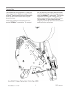
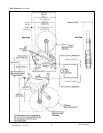
Installation Guidelines
The taping head assembly can be used in converting
existing or in custom made machinery.
It can be mounted for top taping or bottom taping.
Refer to "Box Size Capacities," as well as Figure
2-1 in the Specifi cations section, for the following
points in making such installations:
4. Mounting studs are provided with the taping
head, but special installations may require
alternate means for mounting.
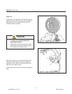
5. Box hold-down or guide skis should be provided
and the taping head mounted so that the side
plates are 6mm [1/4 inch] maximum away from
the ski surface on which the box rides.
Tape Leg Length
Taping heads are factory set to apply standard
70mm [2-3/4 inch] tape legs. The heads can be
converted to apply 50mm [2 inch] tape legs if desired
but both upper and lower heads must be set to ap-
ply the same tape leg length. See "Adjustments –
Changing Tape Leg Length From 70 to 50mm
[2-3/4 to 2 Inches]."
Also, the conveyor speed at which the product
moves through the taping heads, affects the leading
and trailing tape leg length. See "Adjustments sec-
tion – Leading Tape Leg Length Adjustment."
Tape Width Adjustment
Taping heads are factory set to apply 72mm [3 inch]
wide tape. If it is necessary to align the tape or to
apply narrower tapes, refer to "Adjustments – Tape
Web Alignment" for set-up procedure.
Note – AccuGlide™ 3 Upper Taping Head is
supplied with a buffi ng arm guard. Adjustments to
this guard may be required to install the taping head
into some older design 3M-Matic™ case sealers.
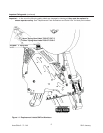
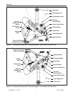
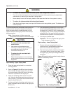
3. Figure 2-1 illustrates the typical mounting
relationship for opposing taping head
assemblies to allow taping of box heights down
to 90mm [3-1/2 inches]. To tape box heights
down to 70mm [2-3/4 inches], the taping heads
must be completely staggered so only one tape
seal is being applied at one time.
• To reduce the risk associated with sharp blade hazards:
− Keep hands and fi ngers away from tape cutoff blades under orange blade guards. The blades
are extremely sharp
WARNING
Important – Always conduct a hazard review to
determine appropriate guarding requirements
when the installation is in an application other
than 3M-Matic
(TM)
equipment
AccuGlide 3 - 3" - NA
2012 January
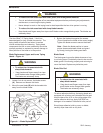
• To reduce the risk associated with
muscle strain:
− Use proper body mechanics when
removing or installing taping heads that
are moderately heavy or may be
considered awkward to lift
CAUTION