


34
13.11.4 Special Set-Up Procedure (continued)
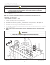
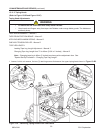
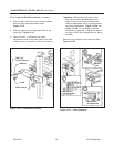
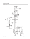
4. Remove M6 x 16 hex hd screw, special washer
and drive belt width adjustment crank -
Figure 13-12.
5. Remove side covers (2) from each side of ma-
chine bed - Figure 13-12.
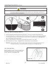
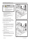
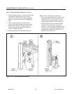
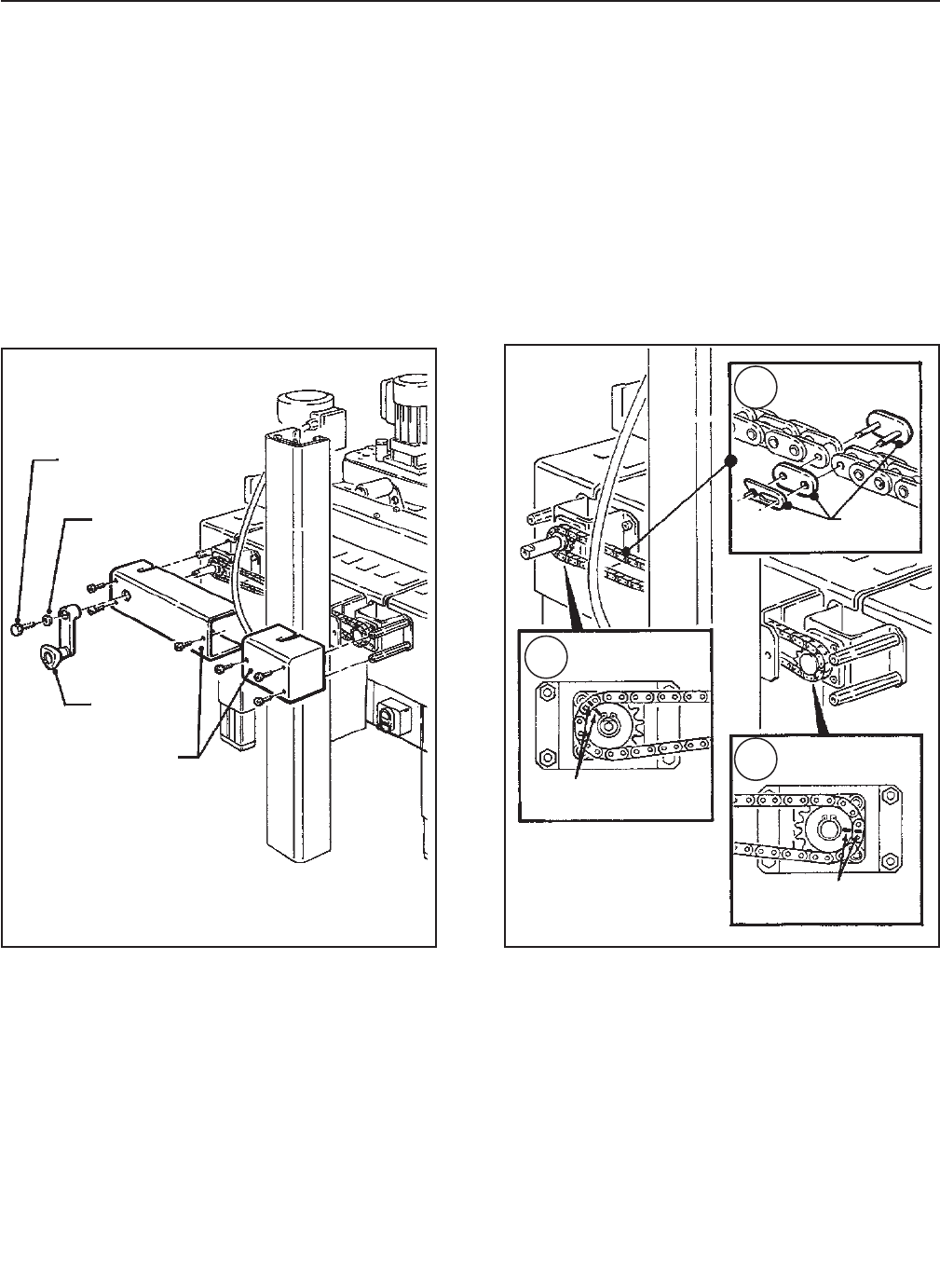
6. Remove chain. If necessary, slip width
adjustment crank on shaft and rotate until chain
master link is in convenient position for removal.
Important – Before removing chain, mark
both front and rear sprockets/chain with
chalk or paint to be sure sprockets/chain
when re-assembled, will be in same position
as before disassembly. Figure 13-13A and
Figure 13-11B. Do not rotate sprockets
once chain is removed. (This would result in
the right and left drive assemblies not being
parallel.)
Remove chain master link and remove chain.
Figure 13-13C.
Figure 13-13 – Chain Removal
Figure 13-12 – Crank/Chain Guards
13-MAINTENANCE - SPECIAL SET-UP (continued)
M6 X 16
Hex Hd Screw
Master
Link
Mark Chain
and Sprocket
Mark Chain
and Sprocket
Washer
Crank
Side Covers
A
C
B
2011 September
800a3-NA