


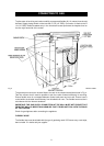
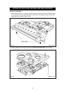

ELECTRICAL CONNECTION IS LOCATED AT THE TOP RIGHT HAND SIDE OF THE
APPLIANCE, BEHIND SIDE PANEL. DURING INSTALLATION REMOVE THE RIGHT HAND
SIDE PANEL TO CONNECT ELECTRICAL SUPPLY.
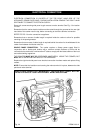
Remove 6 screws securing side panel to gain access to mains terminal. See Fig. 3 for location
of cover.
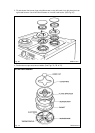
Remember that the mains electrical cable must be routed through the grommet at the rear right
hand side of the cooker near the top, before connecting to the mains terminal connection.
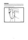
REFER TO FIG. 2 for wire connection to appliance.
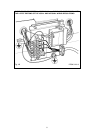
Remember that an excess of cable length is required inside the cooker to allow for possible
servicing of the spark generator.
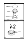
Remember that an excess of cable length is required behind the cooker for the withdrawal of the
cooker from between the kitchen units etc.
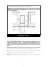
SINGLE PHASE CONNECTION - The cooker requires a 30amp power supply fitted in
conjunction with a double pole isolator with a minimum contact clearance of 3mm and be
connected to the mains with a minimum 6mm
2
cable to comply with the latest editions of the local
and national wiring regulations.
THE ISOLATOR MUST NOT BE POSITIONED IMMEDIATELY ABOVE THE COOKER, BUT
MUST BE SITED WITHIN 2 METRES OF THE APPLIANCE.
Replace the right hand side panel once electrical connection has been made and replace fixing
screws.
NOTE: Ensure that the insulation card covering the mains terminal is in place, between the side
panel and mains terminal.
7
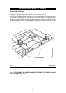
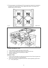
ELECTRICAL CONNECTION
Fig. 2A DESN 513312
SINGLE PHASE CONNECTION - MINIMUM 6mm
2
CABLE AND MUST COMPLY WITH THE
LATEST EDITIONS OF LOCAL AND NATIONAL WIRING REGULATIONS.