


7
Range has been grounded at the factory to the center
(nickel plated) terminal of the terminal block in
accordance with the National Electrical Code (section
2560). When a separate ground is required by local code,
disconnect the grounding strap from the terminal block.
Ground frame by connecting a grounding wire to range
frame using only the grounding screw removed from the
grounding strap.
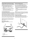
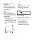
Power lead
connect wire
with black or red insulation
and brass terminal
Power terminals
(240 V)
Ground
strap
Neutral terminal
connect wire
with white insulation
Terminal Block
Terminal block is approved for copper wire connection
only, NOT aluminum wiring. If aluminum house wiring
is to be connected, the following procedure is suggested.
1. Connect length of copper building wire to range
terminal block with ring terminals.
2. Splice copper wires to aluminum wiring using
connectors which are designed certified by
Underwriter’s Laboratories and recognized for joining
copper to aluminum. Follow the connector
manufacturer’s recommended procedure.
3. Wire used, location and enclosure of splices must
conform to local codes.
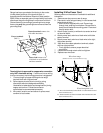
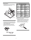
Installing 3-Wire Power Cord
Refer to power cord instructions if available for additional
information.
1. Remove rear wire cover on rear of range.
2. Place strain relief (winged clamp) in cord access hole
below terminal block.
• Strain relief is supplied with cord. Place wings
through hole, entering from bottom. Screw holes in
clamp should be below mounting panel. Place cord
through strain relief.
3. Attach neutral (center) or white wire to center terminal
on terminal block.
4. Attach power lead, red wire or black wire to left side
power terminal.
5. Attach power lead, red wire or black wire to the right
side power terminal.
6. After wires have been placed on terminals, attach
with hex nuts provided.
• Firmly tighten to ensure proper electrical
connection.
7. Place screw through strain relief and tighten.
8. Replace rear wire cover.
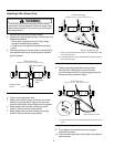
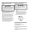
Wires from power cord
Wires from range
(Number of wires on each terminal can vary)
A
A
B
A—Power lead terminal (Connect black or red insulated wire and
secure with brass nut.)
B—Neutral terminal (Connect insulated white insulated wire and
secure with brass nut.)
Installing 3-wire Power Cord