


(©October, 2006)
CyberChiller Series Installation, Operation & Maintenance Manual
2-3
2.5 Piping Connections
2.5.1 Process Supply Fluid Lines
Coolant fluid supply and return lines are connected
from the equipment being cooled to the CyberChiller
via copper sweat fittings provided in the pump section.
2.5.2 Refrigerant
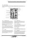
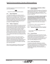
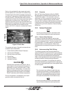
2.5.2.1 Split Air Cooled Systems
Split air-cooled systems with a remote condenser will
require field refrigeration piping. (See Figure 3.) All split
systems are shipped with a dry nitrogen charge of 50
psig.
Split systems coupled with a remote condensing unit
will require a copper discharge and a copper liquid line.
All refrigeration piping should be installed with high
temperature soldered joints. Use standard refrigeration
practices for piping supports, leak testing, dehydration
and charging of the refrigeration circuits. The refrigera-
tion piping should be isolated from the building by the
use of vibration isolating supports. To prevent tube
damage when sealing openings in walls and to reduce
vibration transmission, use a soft flexible material to
pack around the tubes.
Clear all pipe connections of debris and prepare the
connections for soldering. Use only "L" or "K" grade
refrigerant copper piping. Be careful not to allow
solder/piping debris to get inside refrigerant lines.
Silver solder containing a minimum of 15% silver is
recommended. Dry nitrogen should be flowing through
the tubing while soldering at a rate of not less than 1-2
CFM (.03 - .06 M
3
/minute).
Refrigerant lines for split systems must be sized
according to the piping distance between the evapora-
tor and the condenser. Each valve, fitting and bend in
the refrigerant line must be considered in this calcula-
tion. Refer to the following charts for standard equiva-
lent lengths, in feet, of straight pipe.
Oil traps must be included in the discharge line every
20 feet in the vertical risers and the refrigerant lines
must be sloped ¼ inch for every 10 feet in the horizon-
tal lines to ensure proper oil return to the compressor.
An inverted trap is required on the discharge line of the
remote condenser to help prevent oil and liquid from
flooding back to the compressor.
VALVE
R
O
T
O
L
OCK
ROTOLOCK
S
ERVI
C
E P
O
R
T
S
ERVI
C
E P
O
R
T
RELIEF VALVE
PRE
SSU
R
E
(
OPTIONAL
)
S
EE N
O
TE
2
VALVE
ELE
C
TR
O
NI
C
H
O
T
G
A
S
BYPA
SS
EQ
UALIZER LINE
VALVE
EXPAN
S
I
ON
SO
LEN
O
ID VALV
E
LI
Q
UID LIN
E
S
I
G
HT
G
LA
SS
DRIER
/S
TRAINE
R
S
ERVI
CE
P
O
R
T
RE
C
EIVE
R
CO
NTR
OL
FAN
S
PEE
D
CO
NDEN
S
E
R
CS
INTER
CO
NNE
C
TIN
G
FIELD PIPIN
G
BY
O
THER
S
INTER
CO
NNE
C
TIN
G
FIELD PIPIN
G
BY
O
THER
S
H
O
T
G
A
S
SO
LEN
O
ID VALV
E
C
HE
CK
SC
HRADE
R
H
I
G
H PRE
SSU
R
E
LIMIT
S
WIT
CH
H
P
LO
W PRE
SSU
R
E
L
IMIT
S
WIT
CH
EVAP
2
)
PRESSURE RELIEF VALVE MUST BE PIPED TO EXIT THE CABINET
.
1
)
LOCATE AUTOMATIC AIR VENT AT HIGHEST POINT OF SYSTEM
.
N
O
TE
S:
INLET
OU
TLE
T
Figure 3- Typical Piping Air Cooled System