


(©October, 2006)
CyberChiller Series Installation, Operation & Maintenance Manual
2-8
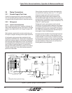
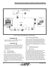
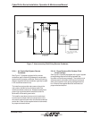
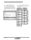
2.6.4.1 Air-Cooled Split System Remote
Condenser
See Figure 7. Systems equipped with a remote
condenser require field wiring between the evaporator
system and the remote condenser. Refer to the wiring
diagram supplied with the condenser (typically located
in the condenser electric box).
The installer must provide main power wiring to the
main power distribution block located within the
remote condenser control box. A separate equipment
ground lug is provided within the electrical box for
termination of the earth ground wire.
The installer must also wire two control conductors
from the terminal board within the evaporator unit to
the control terminal board within the remote condenser
control box. Refer to the supplied electrical schematic
for proper wire terminations.
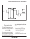
2.6.4.2 Glycol Systems With Outdoor Fluid
Pump Package
See Figure 8. Systems equipped with a glycol system
pump package require field wiring between the
drycooler unit and pump package. The installer must
wire two control conductors from the terminal board
within the drycooler to the pump package electrical
box. Refer to the supplied electrical schematic for
proper wire terminations.
Figure 7- Interconnecting Field Wiring Remote Condenser
AIR
COO
LED
CO
NDEN
S
E
R
WITH NFPA 70, N.E.C.
)
INTER
CO
NNE
C
TIN
G
FIELD WIRIN
G
(
T
O
BE INSTALLED IN ACC
O
RDANC
E
24VA
C
2
08
-
5
7
5
V
/3
PH
/60
H
z
MAIN P
O
WER
SU
PPLY
2
08
-
5
7
5V
M
AIN P
O
IN A
CCO
RDAN
C
E WIT
H
INTER
CO
NNE
C
TIN
G
FIELD
WIRING
(
TO BE INSTALLE
D
NFPA 70, N.E.C.
)