


(©October, 2006)
CyberChiller Series Installation, Operation & Maintenance Manual
2.7.6 Head Pressure Controls
2.7.6.1 Air-Cooled Systems
2.7.6.1.1 Condenser Fan Speed
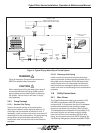
Remote air-cooled condensers use variable speed
condenser motor control to maintain head pressure.
The variable speed motor is located closest to the
header end of the condenser. The fan speed control is
a continual modulation of the motor's speed. As the
condenser discharge pressure rises, the fan speed
increases, cooling the condenser which lowers the
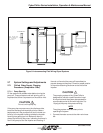
discharge pressure. The controller is mounted in an
electrical box for field installation or could be pre-
packaged with the outdoor condenser. Mount the
condenser control box on the header end of the
condenser. The fan speed controller requires no
adjustments.
Ensure the wiring to the condenser is in accordance
with appropriate codes and the electrical schematic.
On systems with more than one fan on the condenser,
the remaining motors cycle on and off through addi-
tional thermostat(s).
2.7.6.2 Water/Glycol-Cooled Systems
2.7.6.2.1 Head Pressure Regulating Valve
In a water/glycol condenser, condensing temperature
is maintained by the liquid flowing through a regulating
valve and then into a brazed plate liquid-cooled
condenser. The regulating valve opens to increase
liquid flow as the pressure rises (or closes as the
refrigerant pressure falls). The regulating valve is
factory set for the correct condensing temperature
however, it can be adjusted to increase or decrease
the condensing temperature as follows:
Head pressure regulating valves are available in 2-way
or 3-way configurations. 3-way valves are available with
pressure ratings of 150 and 300 psig. The location and
method for adjusting the valves for condensing pres-
sure differs with the valve types. To increase the
condensing temperature, decrease water/glycol flow.
To decrease the condensing temperature, increase the
water/glycol flow. A directional arrow is stamped on the
metal housing of the valve stem.
2.7.7 Thermal Expansion Valve
CyberChiller units utilize a thermal expansion valve
(TEV) to control the flow of refrigerant entering the
evaporator in order to maintain a constant superheat of
the refrigerant vapor at the outlet of the evaporator.
Superheat is the difference between the refrigerant
vapor temperature and its saturation temperature at
that pressure. By controlling superheat, the TEV
keeps nearly the entire evaporator surface active while
not permitting liquid refrigerant to return to the com-
pressor.
The standard superheat is factory set at 12-20°F and
should not need adjustment. If adjustment should be
required, remove the cap from the valve. Turn the
adjusting stem clockwise to increase the superheat
and counter clockwise to decrease the superheat.
2.7.8 Hot Gas Bypass
The hot gas bypass system provides some modulated
capacity control and freeze protection. The hot gas
bypass system consists of a discharge bypass valve
that allows some hot gas from the compressor
discharge line to flow directly to the evaporator, in
order to maintain the fluid leaving temperature.
The hot gas bypass system also provides freeze
protection for the evaporator coil by limiting the
minimum refrigerant pressure, thereby preventing the
surface temperature of the evaporator coil from drop-
ping into the freezing range.
The hot gas bypass valve is automatically controlled
by the Chiller’s unit mounted controller. The hot gas
bypass valve will begin to open, allowing hot gas
refrigerant to enter the evaporator once the leaving
water temperature falls to the leaving water tempera-
ture setpoint.
2-13