


(©October, 2006)
CyberChiller Series Installation, Operation & Maintenance Manual
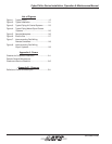
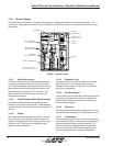
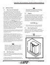
1.2.3 General Design
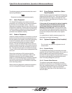
The CyberChiller is divided into 3 areas; a pump section, a refrigeration section and an electrical section. The
housing is a frame type construction. Figure 1 depicts the internal layout of the unit and the location of the major
components.
PUMP #2
(OPTIONAL)
SCROLL COMPRESSORS
HEAT EXCHANGERS
(EVAPORATORS)
ELECTRIC BOX
RECEIVERS
(BEHIND COMPRESSORS)
EXPANSION TANK
(BEHIND PUMP #2)
AIR VENT
HEAT EXCHANGERS
(CONDENSERS- NOTE 1)
NOTE 1: PROVIDED WITH
WATER/GLYCOL COOLED UNITS.
PUMP #1
AIR SEPARATOR
Figure 1- Typical Layout
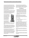
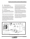
1.2.3.1 Electric Box Access
The electrical components are protected behind dual
hinged access doors located on the left side of the
unit. The access doors are safety interlocked with the
service disconnect switch preventing the doors from
opening when the switch in the “On” position. The
switch must be turned “Off” to gain access to the
electrical components.
1.2.3.2 Circuit Breakers/ Motor Start Protectors
Individual overload protection is provided by circuit
breaker(s) and motor start protectors. These switches
must be manually re-set once the overload condition is
cleared.
1.2.3.3 Pumps
Multi-stage centrifugal pumps are located in the right
side of the unit to circulate the coolant through the
system. A hinged access door is located on the right
side of the unit. This door may be opened to gain
access to the pump section.
1.2.3.4 Expansion Tank
An expansion tank has been provided on the chilled
water side of the unit to compensate for thermal
expansion of the coolant. An air vent is mounted on
top of the fluid separator.
1.2.3.5 Heat Exchangers
Constructed of 316 stainless steel with brazed plate fin
construction, the evaporator heat exchangers are for
the exchange of heat from the process water/glycol
coolant to the refrigerant.
1.2.3.6 Receivers
Receivers are provided for each refrigeration circuit for
storage of excess refrigerant in the refrigeration cycle.
1.2.3.7 Compressors
The compressors used in this unit are scroll compres-
sors mounted inside the unit on vibration absorbers to
eliminate noise and vibration during operation. The
scroll compressor is designed around two identical
spirals or scrolls that, when inserted together, form
crescent shaped pockets. During a compression
1-2