


(©October, 2006)
CyberChiller Series Installation, Operation & Maintenance Manual
3-1
3.0 START-UP/COMMISSIONING
3.1 Operation
For new installations, ensure the unit is ready to
operate by going through the Checklist for Completed
Installation, located in Appendix A, prior to start-up.
NOTE
A Warranty Registration and Start-Up Checklist
is provided with the unit data package. It should
be completed during start-up and sent to SATS.
This checklist should be used as a guideline for
items that need to be confirmed during start-up.
Start-up must be performed by a journeyman, refrig-
eration mechanic or an air conditioning technician.
3.2 Step by Step Start-Up Instructions
1. Replace all equipment removed prior to performing
start-up checks.
2. Apply power to start the CyberChiller system at
the main power disconnect switch.
NOTE
The compressor(s) may have a time delay on start-up.
Both refrigeration circuits must be tested at start-up.
There are several ways to force the second circuit
into operation. Refer to the separate controller opera-
tion instructions sent with your unit in the data pack-
age.
3. Test cooling operation by adjusting the leaving fluid
temperature setpoint. The compressor should
come on and the chilled water supply should
gradually drop in temperature.
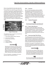
3.2.1 Operational Description
3.2.1.2 Compressor
1. Compressor starts.
2. The compressor takes low pressure, low tempera-
ture gas and compresses it to a high temperature,
high pressure gas.
3. The refrigerant then flows to the condenser coil.
The high temperature, high-pressure gas from the
compressor is cooled by the flow of water/glycol/
air through the condenser coil and is changed into
a low temperature, high-pressure liquid.
4. The low temperature, high-pressure liquid refriger-
ant then flows to the receiver. The receiver acts as
a storage tank for the liquid refrigerant that is not
in circulation.
5. The refrigerant drier/strainer removes any moisture
(water vapor) or impurities that may be carried by
the liquid refrigerant.
6. The refrigerant then flows through the liquid sight
glass. This device indicates the presence of
moisture and state of refrigerant in the system.
7. The liquid line solenoid valve controls the flow of
refrigerant before going to expansion valve, which
controls the amount of liquid refrigerant to the heat
exchanger. The expansion valve senses the
temperature and pressure of the refrigerant as it
leaves the heat exchanger. By use of a sensing
bulb and an external equalizer line the valve
constantly adjusts the flow of liquid refrigerant to
the heat exchanger.
8. As the liquid refrigerant leaves the expansion valve
it enters the heat exchanger. The evaporation of
the liquid refrigerant within the heat exchanger
removes heat from the water coolant.
9. The refrigerant gas is then drawn back to the
compressor and the cycle is repeated.
10. Hot gas from the compressor discharge line is
injected into the inlet of the heat exchanger by the
hot gas bypass regulator valves. The system
controller signals the hot gas regulator valves to
proportionally vary the rate of hot gas being
injected into the inlet of the heat exchanger as a
function of the supply coolant temperature sensed.
The hot gas will mix with the refrigerant from the
expansion valve. The expansion valve will meter
the flow of liquid refrigerant as needed to maintain
super heat to approximately 9° - 11°F.
11. The hot gas valve(s) act together with the expan-
sion valve(s) to control the temperature of the
supply coolant.
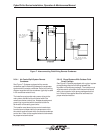
3.2.1.3 Coolant System
The water coolant system is a closed loop re-circulat-
ing system. The pressurized supply coolant flows
through the electronics equipment removing heat and
then is returned to the expansion tank inside the
CyberChiller. The fluid is pumped from the expansion
tank through the system heat exchanger where heat is
removed from the fluid. After cooling, the fluid is re-