


(©October, 2006)
CyberChiller Series Installation, Operation & Maintenance Manual
2-12
CAUTION
POE oil is used in systems with R-407C
refrigerant. POE oil quickly absorbs moisture
when exposed to air. High POE oil moisture
levels react with refrigerant to form acid, which
results in system contamination. Keep entire
system sealed as much as possible and
minimize exposure of POE oil to outside air.
Familiarize yourself with the charging proce-
dures discussed in section 2.7.3 of this
manual. Instead of adding R-22 vapor to the
suction port as described under “Preparing
System For Charging”, the initial charge will
be performed by introducing R-407C liquid to
the discharge side of the compressor.
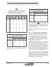
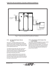
PREPARING SYSTEM FOR CHARGING
1. With all the system piping connections made,
perform a dry nitrogen leak detection test on the
system. Using dry nitrogen only, pressurize the
system to 150 psig. Since there is no refrigerant
in the system to detect, leaks may be detected
by observing the standing pressure.
2. After ensuring there are no leaks, evacuate the
system to 50 microns and hold the vacuum for 2
hours.
3. Break the vacuum by supplying R-407C liquid to
the discharge port near the compressor until the
pressure is raised to about 50 psig. This small
holding charge allows the low pressure switch to
“make” through the process of fine tuning the
system charge.
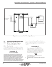
FINE TUNING THE SYSTEM CHARGE
4. Disconnect the refrigerant cylinder from the
discharge side of the compressor and connect it
to the suction side.
5. Start the system and use the microprocessor
controller to lower the supply water temperature
setpoint 3-5°F below actual water temperature,
ensuring cooling remains on as the unit is
charged.
6. Allow the discharge pressure to rise to 225-280
psig and hold it constant. On cool days it may be
necessary to restrict the airflow across the
condenser (or reduce the water glycol flow), to
raise the pressure.
7. Slowly meter R-407C liquid refrigerant through the
suction side while watching the sight glass to clear
of bubbles.
CAUTION
Add liquid refrigerant slowly to prevent the refrigerant
oil from “washing out” of the compressor.
8. While monitoring the sight glass, take a sub-
cooling temperature reading on the output side of
the condenser. The sub-cooling temperature
should be 10-12°F.
9. If necessary, add liquid refrigerant to maintain
adequate sub-cooling temperature.
10. Take a superheat reading on the suction line 6"
from the compressor. The superheat should be 12-
20°F.
2.7.5 High/Low Pressure Limit Switch
CyberChiller units utilizing thermal expansion valves
are equipped with hermetically sealed high-pressure
and low-pressure switches. These switches are preset
by the manufacturer and cannot be adjusted. The high
pressure switch will open the control circuit to disen-
gage power to the compressor contactor if the
discharge pressure rises above a specific pressure.
The high pressure switch also triggers an alarm signal
at the controller. To restore operation of a compressor
after shut down due to high or low pressure, re-set the
alarm at the remote panel. If a compressor was
disabled due to high pressure conditions, a manual
reset of the high pressure safety switch is also
required. The high-pressure switch opens at 410 psig
and has a manual reset.
The Low pressure switch will open the control circuit
to the microprocessor digital input to disengage power
to the compressor contactor if suction pressure drops
below a specific pressure. The microprocessor will
ignore the absence of this signal during the cold start
delay period after starting of a compressor. Should
this signal continue to be absent or open after the
cold start period, the affected compressor will be shut
down with an alarm indication at the controller. The
low-pressure switch opens at 10 psig (± 4) and closes
at 32 psig (± 5) and has an automatic reset.