


(©October, 2006)
CyberChiller Series Installation, Operation & Maintenance Manual
2-7
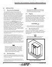
Each unit is provided with main power and control
terminal positions for connection of the field-wiring.
The opening for the conduit is located in the floor of
the cabinet. A label stating "MAIN POWER INPUT" is
in close proximity. The main power wires are termi-
nated at the line side of the service disconnect switch
located within the electric box. (See Figure 6.) A
separate equipment ground lug is provided within the
electrical box for termination of the earth ground wire.
Terminals are available as an interface to a dry
contact, (N.O./N.C.), relay for a remote alarm status
signal.
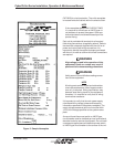
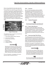
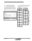
Figure 6- Electric Box
The number call outs in Figure 6 coincide with the
numbered items listed below.
1. Power Switches/Motor Starter Protectors
2. Control Circuit Breakers
3. Service Disconnect Switch
4. Ground Lug
5. Control I/O Board
6. Interface Terminals
CAUTION
Improper wire connections will result in the re-
verse rotation of the pumps and compressor (if
applicable) and may eventually result in dam-
age to the scroll compressor. To correct this
problem, exchange any two of the incoming main
power wires at the main power circuit breaker.
Do NOT rewire the unit's individual components.
Prior to unit operation, an adequate unit-to-earth
ground must be connected to the unit.
2.6.2 Controls
Stulz Air Technology Systems offers the C6000
Microprocessor as the standard controller for the
CyberChiller system. If it is mounted on the unit
(standard), no utility connection is required. As an
option a factory supplied display may be remote
mounted. A six-conductor cable harness is provided for
interconnect wiring. Refer to the electrical drawings
supplied with your unit for details on interconnecting
field wiring.
2.6.3 Optional Equipment
NOTE
All wiring must be provided in accordance with
local and national electrical code requirements.
2.6.3.1 Remote Water Detector
The optional remote water detector requires two
conductors to be wired to the control terminal board
within the unit electrical box. The wire insulation must
be rated at 600V. The water detector includes screw
type terminals for wire connections. Refer to the
supplied electrical schematic for proper wire termina-
tions.
2.6.4 Interconnecting Field Wiring
The following system interconnecting field wiring
sections detail the wiring required for a typical system.
Additional control conductors may be required depend-
ing on the options purchased with the equipment.
Refer to the supplied electrical drawings to determine
the total number of interconnecting conductors
required for your system. It is important to note that
the control transformer(s) supplied with the equipment
are sized and selected based upon the expected loads
for each system.
CAUTION
Do not connect any additional loads to the sys-
tem control transformers. Connecting additional
loads to the factory supplied control transformer
may result in overloading of the transformer, which
will cause the transformer circuit breaker to trip.
NOTE
All wiring must be provided in accordance with
local and national electrical code requirements.
1
2
3
4
5
6