


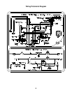
Specifications
Operating Limits
AC Mode: 132 volts AC max. - 108 volts AC min.
DC Mode: 15.4 volts DC max. - 11.5 volts DC min.
Gas Mode: 11" W.C. max. - 10.5" W.C. min.
15.4 VDC max. - 10.5 VDC min.
Current Draws
AC Heatin
g
Element - 1.3 amp @ 110 volts AC
1.4 amps @ 120 volts AC
DC Heatin
g
Element - 11.7 amps @ 12 volts DC
13.6 amps @ 14 volts DC
I
g
nition Reli
g
hter - 150 milliamps durin
g
i
g
nition
100 milliamps stead
y
state
Ventilation Fan - 240 milliamps
Ratings
LP Gas Mode: 640 BTU/Hr. Input
11" W.C. Gas Suppl
y
.010" Orifice
(
LP10
)
AC Mode: 110 volts AC - 140 watts
DC Mode: 12 volts DC - 140 watts
Fuse Replacement Data
AC Circuit: 3 amp T
y
pe 3AG
(
1/4" x 1/4"
)
Norcold Part No.: 61654622
DC Circuit: 20 amp T
y
pe 3AG
(
1/4" x 1/4"
)
Norcold Part No.: 61440522
Gas Circuit: 1 amp T
y
pe 3AG
(
1/4" x 1/4"
)
Norcold Part No.: 618079
General Information
This refrigerator is not intended to be operated as a
Free-Standing refrigerator (i.e. the products of combus-
tion must be completely isolated from the living area)
or installed in such a way as to conflict with these
installation instructions. Unapproved installations could
result in safety risks or performance problems.
The model 3163 is desi
g
ned for built-in installation and
operates on propane
g
as, 120 volts AC, or 12 volts DC.
The propane
g
as mode of operation is that of a sealed
combustion unit. A sealed combustion installation util-
izes a sin
g
le fresh vent-air intake/exhaust assembl
y
to
suppl
y
fresh air to the burner and to remove the prod-
ucts of combustion. This insures the products of com-
bustion are isolated from the livin
g
area of the vehicle.
The vent-air intake/exhaust assembl
y
is routed throu
g
h
the vehicle’s outside wall and is connected to the
refri
g
erator’s burner assembl
y
and exhaust flue tube b
y
flexible pipin
g
. The vent-air intake/exhaust assembl
y
used for this installation has been certified for this
refri
g
erator and
must not
be modified.
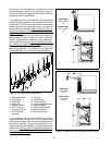
Direct Vent Requirements
Interior Ventilation
The refri
g
erator’s coolin
g
s
y
stem re
q
uires a continual
air flow to maintain proper refri
g
eration. An inlet and
exhaust vent is re
q
uired to insure ade
q
uate air flow.
The refri
g
erator is e
q
uipped with an inlet vent located
at the bottom front of the refri
g
erator. The installer is
re
q
uired to provide the exhaust vent. The exhaust vent
must have a cross sectional area of 30 s
q
uare inches
minimum. The exhaust vent is to be installed above the
top surface of the refri
g
erator so as not to trap hot air
g
enerated b
y
the coolin
g
unit. The refri
g
erator is
e
q
uipped with a DC ventilation fan to assist the air flow
across the refri
g
erator’s coolin
g
s
y
stem while operatin
g
the refri
g
erator in the Gas mode.
Ventilation Fan
A thermostat controlled mechanical fan is used to
move air across the refri
g
erator’s coolin
g
s
y
stem. The
thermostat is calibrated to activate the fan whenever
the vehicle’s interior temperature reaches 85 de
g
rees
or hi
g
her.
When leavin
g
the vehicle unattended, it is advisable
to leave windows or roof exhaust vents open to main-
tain the vehicle’s interior temperature below 85 de-
g
rees. This will allow the refri
g
erator to operate
efficientl
y
, minimize fan operation, and limit current
draw from the batter
y
.
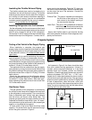
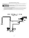
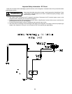
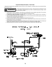
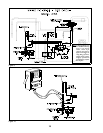
Installing the Vent-Air Intake/Exhaust Assy
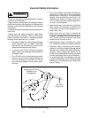
Improper location and installation can cause injury or
property damage. This refrigerator and it’s vents are
design certified by the American Gas Association and
the Canadian Gas Association. Any deviation or sub-
WARNING
WARNING
2