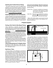
stitution will void the agencies’ certifications and the
Norcold warranty. Refer to this manual for proper in-
structions. Install the refrigerator and vents as directed
by Norcold without modification.
The clearance from the refri
g
erator’s left side
(
facin
g
the front of the refri
g
erator
)
to the vehicle’s exterior wall
is important. This is the area in which the inlet and outlet
flexible pipin
g
will be connected to the vent terminal
housin
g
durin
g
installation.
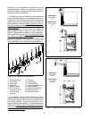
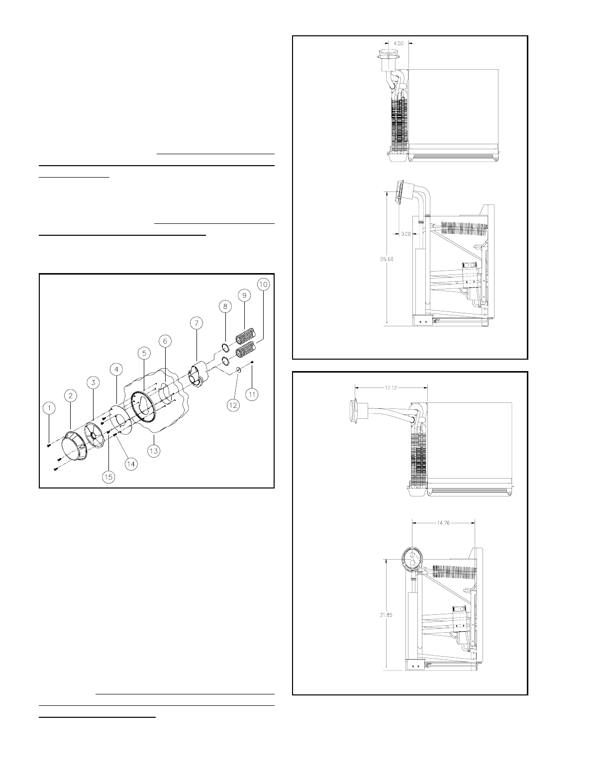
Refer to Figures 3 and 4 for
maximum clearances from refrigerator cabinet to vehi-
cle exterior wall.
The wall thickness the vent terminal housin
g
will
accommodate is .030" minimum to 1.250" maximum.
Fi
g
ure 2 illustrates the confi
g
uration of the openin
g
for
the vent terminal housin
g
.
Do not make the opening in
the vehicle wall larger than required.
The clearance
should be enou
g
h for the terminal housin
g
to pass
throu
g
h the openin
g
. If the openin
g
is too lar
g
e, the
outer
g
asket will not cover the vent housin
g
openin
g
.
It is imperative that the wall openin
g
for the vent
terminal housin
g
not be too low. The flexible pipin
g
(
inlet and outlet pipes
)
must rise from the refri
g
erator to
the terminal housin
g
. There are two specific vent-air
intake assembl
y
kits available to accommodate most
installations.
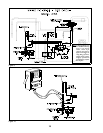
Figures 3 and 4 illustrate two installations
with the maximum flexible piping lengths and the vent
terminal housing locations.
Fi
g
ure 2 - Air Intake/Exhaust Assembl
y
Intake Pipe
max. len
g
th
16"
Exhaust Pipe
max. len
g
th
14"
Fi
g
ure 3 - Kit #617941 Flexible Pipin
g
& Vent Location
Intake Pipe
max. len
g
th
21 3/4"
Exhaust Pipe
max. len
g
th
19 3/4"
Fi
g
ure 4 - Kit #617943 Flexible Pipin
g
& Vent Location
1. Mountin
g
Screw 8. O Rin
g
s
2. Vent Cover 9. Intake Pipin
g
3. Outer Disk 10. Exhaust Pipin
g
4. Inner Disk 11. Lockin
g
Washer Screw
5. Rubber Gasket 12. Lockin
g
Washer
6. Vent Terminal 13. Vehicle Exterior Wall
Housin
g
Cut-Out 14. Mountin
g
Screw
7. Vent Terminal 15. Mountin
g
Screw
Housin
g
3


