


Insulating the Flexible Exhaust Piping
The flexible exhaust pipe must be insulated prior to
installation into the vent terminal housin
g
. The flexible
exhaust pipe connects to the flue tube of the refri
g
era-
tor’s coolin
g
unit and routes to the bottom openin
g
of
the vent terminal housin
g
. Use the non-combustible
insulation material supplied with the vent-air intake/ex-
haust kit.
Do not insulate the Air Intake pipe.
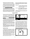
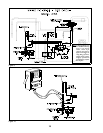
Installing Refrigerator into the Enclosure
Set the refri
g
erator into the enclosure and slide it back
enou
g
h to connect the
g
as suppl
y
pipin
g
to the manual
shut-off valve located at the top of the refri
g
erator.
Connect the 12 volt DC suppl
y
to the terminal block also
located at the top of the refri
g
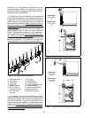
erator. Connect the AC
power cord to the receptacle. Place the "O" rin
g
s onto
the ends of both flexible pipes. Bend the flexible pipes
so the
y
clear the top of the enclosure. Connect the
pipin
g
as follows:
Exhaust Pipe - This pipe is insulated and connects to
the flue tube of the coolin
g
unit. Route
and connect to the bottom openin
g
of
the vent terminal housin
g
.
Intake Pipe - This pipe is
not
insulated and connects to
the burner cover. Route and connect to the
top openin
g
of the vent terminal housin
g
.
Secure both flexible pipes to vent terminal housin
g
with lockin
g
washer and screw. Slide refri
g
erator com-
pletel
y
into enclosure.
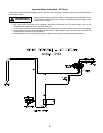
Propane System
Testing of the Vehicle’s Gas Supply Piping
When installation is complete, the propane
g
as
suppl
y
pipin
g
must be inspected and tested for leaks
from the refri
g
erator to the main
g
as suppl
y
tank. Use
a leak detection solution.
Do not test for leaks with an
open flame.
If compressed air is used for leak testin
g
, the pressure
must not exceed 1/2 psi
g
(
14 inches water column
)
.
The appliance and its individual shutoff valve must be
disconnected from the
g
as suppl
y
pipin
g
s
y
stem durin
g
an
y
pressure testin
g
of that s
y
stem at test pressure in
excess of 1/2 psi
g
(
14 inches water column
)
.
The appliance must be isolated from the
g
as suppl
y
pipin
g
s
y
stem b
y
closin
g
its manual shutoff valve durin
g
an
y
pressure testin
g
of the
g
as suppl
y
pipin
g
s
y
stem at
test pressure less than or e
q
ual to 1/2 psi
g
(
14 inches
water column
)
.
Check the
g
as pressure to the refri
g
erator without
other
g
as appliances operatin
g
. The pressure should
not exceed 11 inches water column. With other appli-
ances operatin
g
the pressure should not be less than
10.5 inches water column.
Gas Burner Flame
The
g
as operation of the refri
g
erator is controlled b
y
the correct burner flame which supplies the heat input
to the refri
g
erator’s coolin
g
s
y
stem. The correct burner
flame is dependent upon correct input
g
as pressure
and the burner and burner orifice bein
g
clean. The
propane
g
as pipin
g
and the suppl
y
pressure must be
inspected and tested at least twice a
y
ear. All inspec-
tions and tests must be performed b
y
the propane
g
as
supplier or a
q
ualified service a
g
enc
y
.
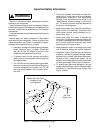
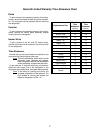
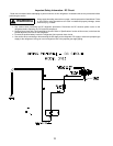
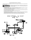
A visual check of the burner flame should be made
re
g
ularl
y
. The burner flame can be observed throu
g
h
the air inlet
g
rille as shown in Fi
g
ure 5.
As illustrated in Fi
g
ure 6, the flame should be sharp
blue with a stable burnin
g
appearance. If there is a
constant
y
ellow component observed or if the flame
appears erratic and unstable, perform the followin
g
inspection. Check the
g
as suppl
y
pressure to insure the
pressure is between 10.5" W.C. min. - 11" W.C. max..
Inspect the Air Intake pipe between the burner and the
vent terminal housin
g
for obstructions. If the
g
as suppl
y
pressure is within specifications, and the Air Intake pipe
is clear of obstructions, clean the burner, orifice, and
coolin
g
unit’s flue tube. Also observe the position of the
flame; it must be centered under the flue tube without
touchin
g
the inner wall of the tube.
Burner Flame
Air Inlet Grille
Fi
g
ure 5
Fi
g
ure 6
4