33
P4102.40
SERVICE (cont.)
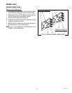
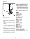
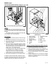
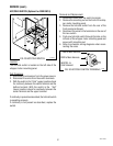
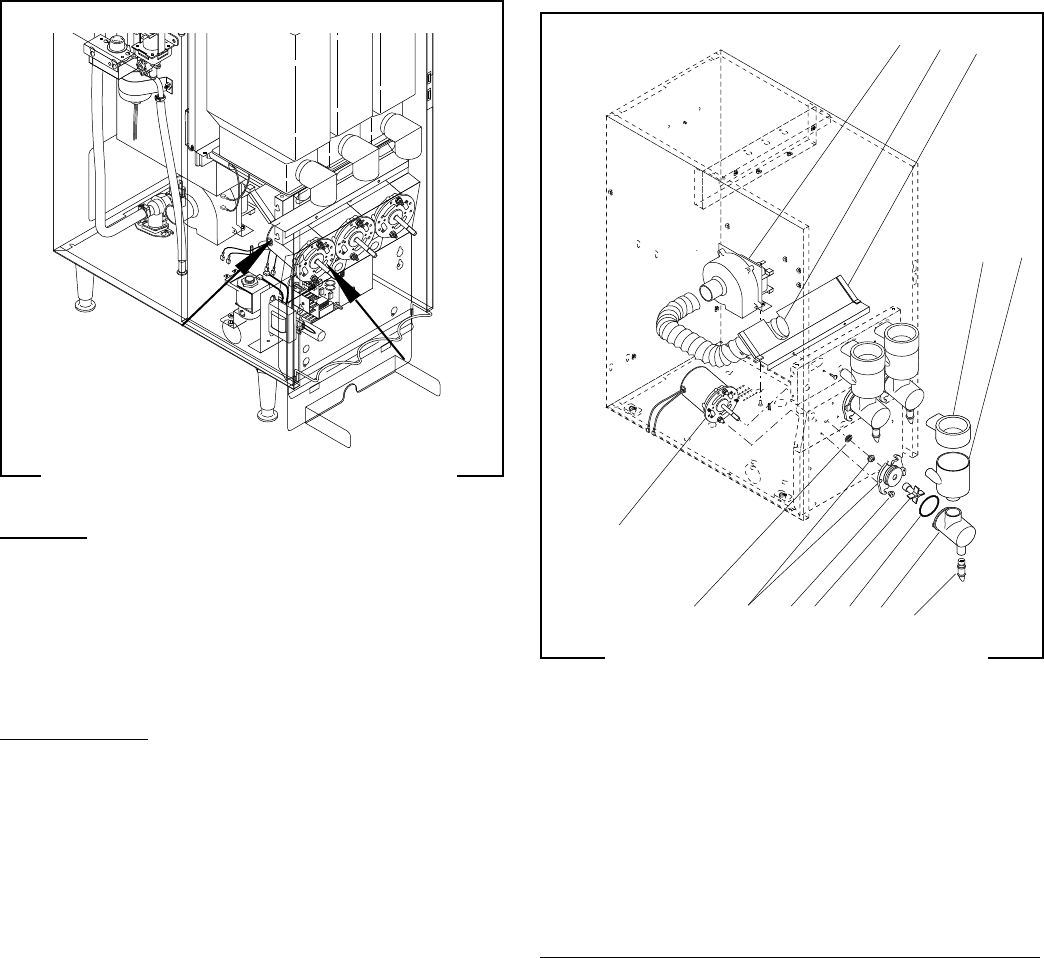
FROTHER AND WHIPPER MOTOR (all Models except -2FD)
FIG. 24 FROTHER AND WHIPPER MOTOR
Location:
The frothers are located behind the dispenser door,
mounted on the whipper motor shaft inside the whipper
chamber.
The whipper motors are located on the back side
of the whipper motor mounting panel.
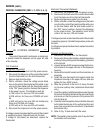
Test Procedure:
1. Check that the rinse/run switch is in the rinse (up)
position.
2. Disconnect the dispenser from the power source.
3. Disconnect both wires from the black leads on the
motor to be checked.
4. Press and hold the appropriate dispense switch
and, with a voltmeter, check the voltage across the
disconnected harness. Connect the dispenser to the
power source. The reading must be:
a) 120 volts ac for two wire 120 volt models, three
wire 120/208 volt and 120/240 volt models.
b) 240 volts ac for two wire 240 volt models.
c) 230 volts ac for two wire 230 volt models.
5. Disconnect the dispenser from the power source.
If voltage is present as described, replace the motor.
If voltage is not present as described, refer to the Wiring
Diagrams and check the dispenser wiring harness
9 8 7 6 5 4 3
10
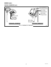
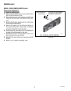
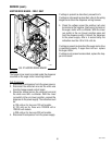
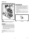
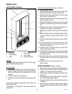
FIG. 25 MIXING/WHIPPER CHAMBER
COMPONENTS
P1630.35
1. Steam Collector
2. Mixing Chamber
3. Dispense Tip
4. Whipper Chamber
5. O-Ring
6. Frother
7. Nut
8. Receptacle w/Seal
9. Slinger
10. Motor Assy.
11. Fan
12. Vacuum Hose
13. Baffle
11 12 13
1 2
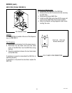
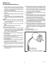
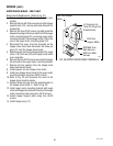
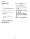
Removal, Cleaning & Replacement (Refer to Fig. 25):
1. Disconnect the dispenser from power.
2. Open the dispenser door and turn elbows up.
3. Remove the steam collectors (1) by pulling forward
and at the same time twisting clockwise.
4. Pull the mixing chamber (2) out of the whipper
chamber (4).
5. Remove dispense tip (3) and twist the whipper
chamber (4) clockwise and pull it off the whipper
chamber receptacle (8).
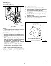
FMD DBC-3 shown
42672 122209


