


42
P1671
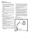
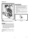
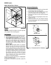
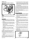
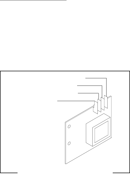
FIG. 35 LEVEL BOARD TERMINALS
TI VIO to Inlet Solenoid Coil
T2 BLK to Main Harness
T3 WHI to Main Harness
T4 PNK to Probe
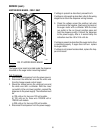
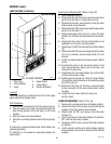
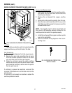
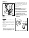
13. Place the probe so that neither end is in contact
with any metal surface of the dispenser.
14. Check the voltage across terminals 1 & 3 with a
voltmeter. Connect the dispenser to the power
source. The indication must be:
a) 120 volts ac for two wire 120 volt models,
b) 120 volts ac for three wire 120/208 volt or
120/240 volt models,
c) 230 volts ac for two wire 230 volt models, after
a delay of approximately 5 seconds.
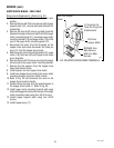
15. Move the probe’s flat end to the tank. The indication
must be 0.
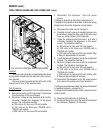
16. Move the probe’s flat end away from the tank. The
indication should again be:
a) 120 volts ac for two wire 120 volt models,
b) 120 volts ac for three wire 120/208 volt or
120/240 volt models,
c) 230 volts ac for two wire 230 volt models, after
a delay of approximately 5 seconds.
If voltage is present as described, reinstall the probe,
the level control board and level probe are operating
properly.
If voltage is not present as described, check the pink
probe wire for continuity.
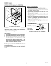
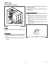
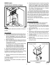
Removal and Replacement:
1. Remove all wires from the level control board.
2. Remove two #8-32 keps nuts holding level control
board to right side of the component bracket.
3. Remove level control board and spacers.
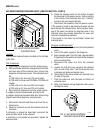
4. Install the new level control board and spacers to
the right side of the component bracket using two
#8-32 keps nuts.
5. Refer to schematic wiring diagrams when recon-
necting the wires.
SERVICE (cont.)
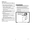
LEVEL CONTROL BOARD AND LEVEL PROBE (cont.)
42672 122209