


47
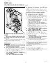
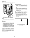
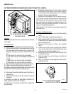
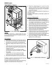
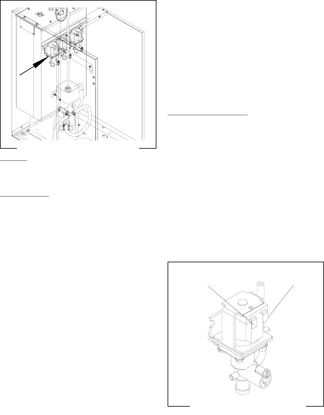
FIG. 45 DISPENSE SOLENOID VALVE
TERMINALS
P1645
SERVICE (cont.)
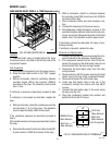
SOLENOID VALVES (DISPENSE) (all Models)
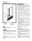
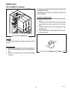
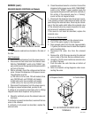
FIG. 44 DISPENSE SOLENOID VALVES
P1637.40
Location:
The dispense solenoids are located on the side of
the tank.
Test Procedures:
1. Disconnect the dispenser from the power source.
2. Disconnect the two wires from the solenoid valve.
With the “RUN/RINSE” switch in the “RINSE” (up-
per) position press the appropriate dispense switch
on front of the door.
3. With a voltmeter, check the voltage across the two
wires. Connect the dispenser to the power source.
The indication must be:
a) 120 volts ac for two wire 120 volt models, three
wire 120/208 volt, and 120/240 volt models.
b) 240 volts ac for two wire 240 volt models.
c) 230 volts ac for two wire 230 volt models.
4. Disconnect the dispenser from the power source,
If voltage is present as described, proceed to #5
If voltage is not present as described, refer to Wiring
Diagrams and check dispenser wiring harness.
5. Check for continuity across the solenoid valve coil
terminals.
If continuity is present as described, reconnect the two
wires to the solenoid.
If continuity is not present as described, replace the
solenoid valve.
6. Check the solenoid valve for coil action. Connect the
dispenser to the power source. With “RUN/RINSE”
switch in the “RINSE” (upper) position press the
appropriate dispense switch and listen carefully in
the vicinity of the solenoid valve for a “clicking”
sound as the coil magnet attracts.
7. Disconnect the dispenser from the power source.
If the sound is heard as described and water will not
pass through the solenoid valve, there may be a block-
age in the tank water outlet before the solenoid valve
or, the solenoid valve may require inspection for wear,
and removal of waterborne particles.
If the sound is not heard as described, replace the
solenoid valve.
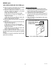
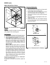
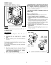
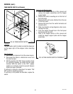
Removal and Replacement:
1. Remove the two wires from the solenoid valve.
2. Turn off the water supply to the dispenser.
3. Drain enough water from the tank (approximately
1.0 gallon) so the water level is below the dispense
valve mounting hole.
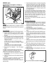
4. Disconnect the water line from the solenoid
valve.
5. Remove the #10-32 screw securing the solenoid
valve to side of the tank. Remove solenoid valve.
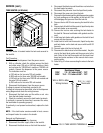
6. Using the #10-32 screw install new solenoid valve
on side of the tank
7. Push the water line onto the tube on bottom of
solenoid valve.
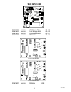
8. Refer to schematic wiring diagrams when recon-
necting the wires.
to Dispense Switch
to Control Board
FMD DBC-3 shown
42672 122209