45
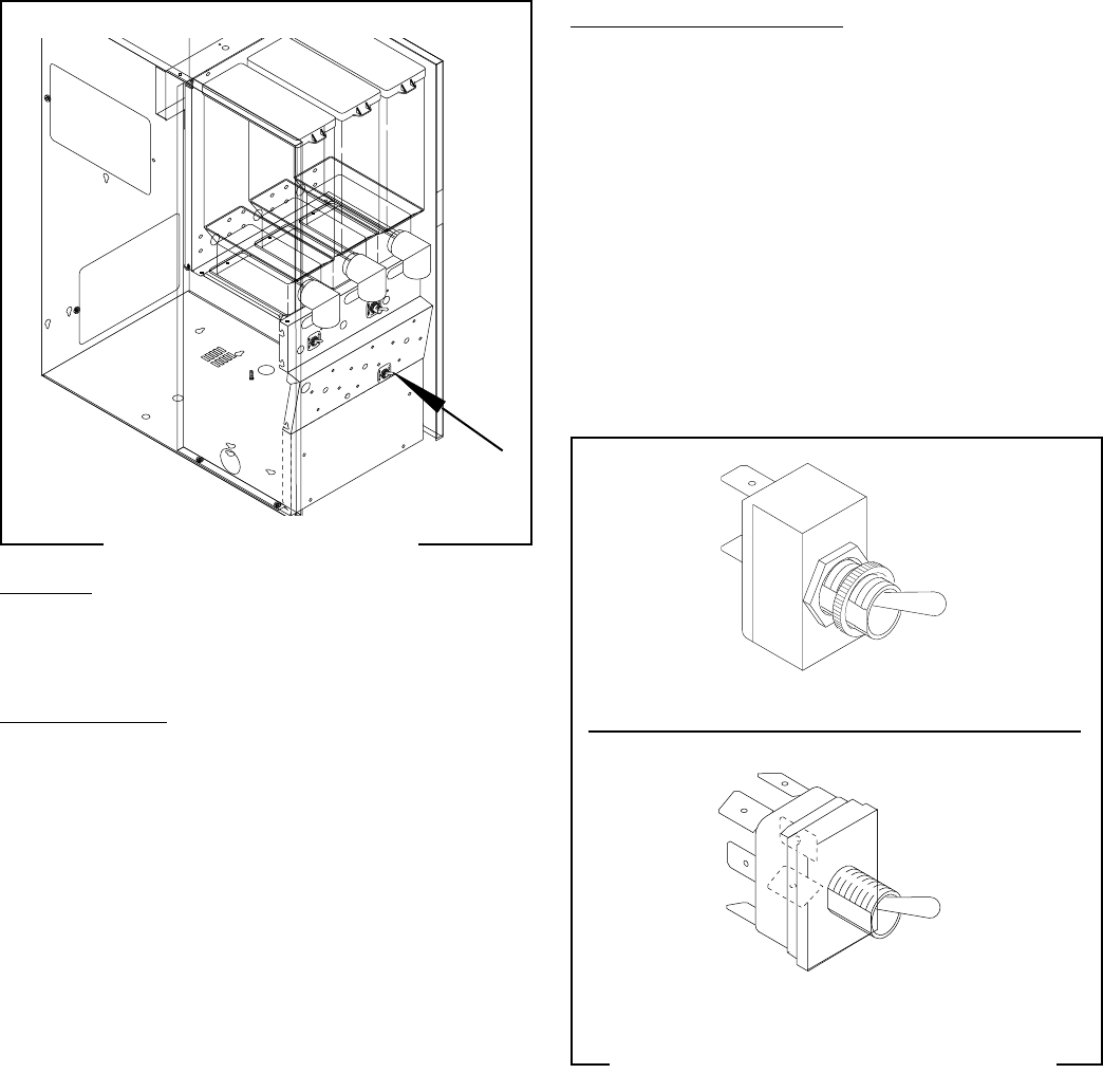
RINSE /RUN SWITCH (all Models)
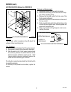
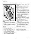
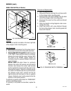
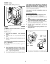
FIG. 40 RINSE/RUN SWITCH
P1684.40
Location:
The rinse/run switch is located on the lower right side
of the whipper motor mounting panel.
Test Procedures:
1. Disconnect the dispenser from the power source.
2. Disconnect the wires from the switch terminals.
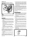
3. Models FMD DBC-2FD and DBC-3: With the switch
in the “RUN” (lower) position check for continuity
between the center and the upper terminal. With
the switch in the “RINSE” (upper) position no
continuity should be present between center and
upper terminals.
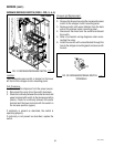
Models FMD-2,-3,-4,-5: Check for continuity
between the center left terminal and left bottom
terminal, also between the center right terminal
and the right bottom terminal with the switch in the
rinse position (upper). Check for continuity across
the center left terminal and the top left terminal,
also between center right terminal and the top
right terminal with the switch in the run position
(lower). Continuity must not be present when the
switch is in the center position.
If continuity is present as described, the “RINSE/RUN”
switch is operating properly.
If continuity is not present as described, replace the
switch.
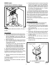
Removal and Replacement:
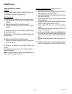
1. Open the dispenser door.
2. Remove the facenut securing the run/rinse switch
to the whipper motor mounting panel.
3. Remove switch with wires attached from the back
side of the whipper motor mounting panel.
4. Disconnect the wires from the switch and discard
the switch.
5. Refer to schematic wiring diagrams when recon-
necting the wires.
6. Install new switch with wires attached through
the hole in the whipper motor mounting panel and
secure with facenut.
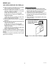
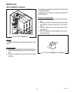
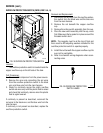
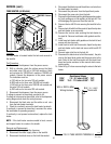
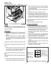
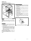
FIG. 41 RINSE/RUN SWITCH TERMINALS
P1456
SERVICE (cont.)
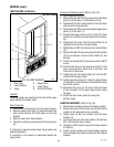
FMD DBC-3 shown
P1644
FMD-2,-3,-4,-5
FMD DBC-3,-2FD
42672 122209


