


51
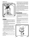
J4
J1
J2
J3
J4
J1
J2
J3
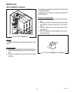
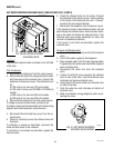
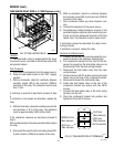
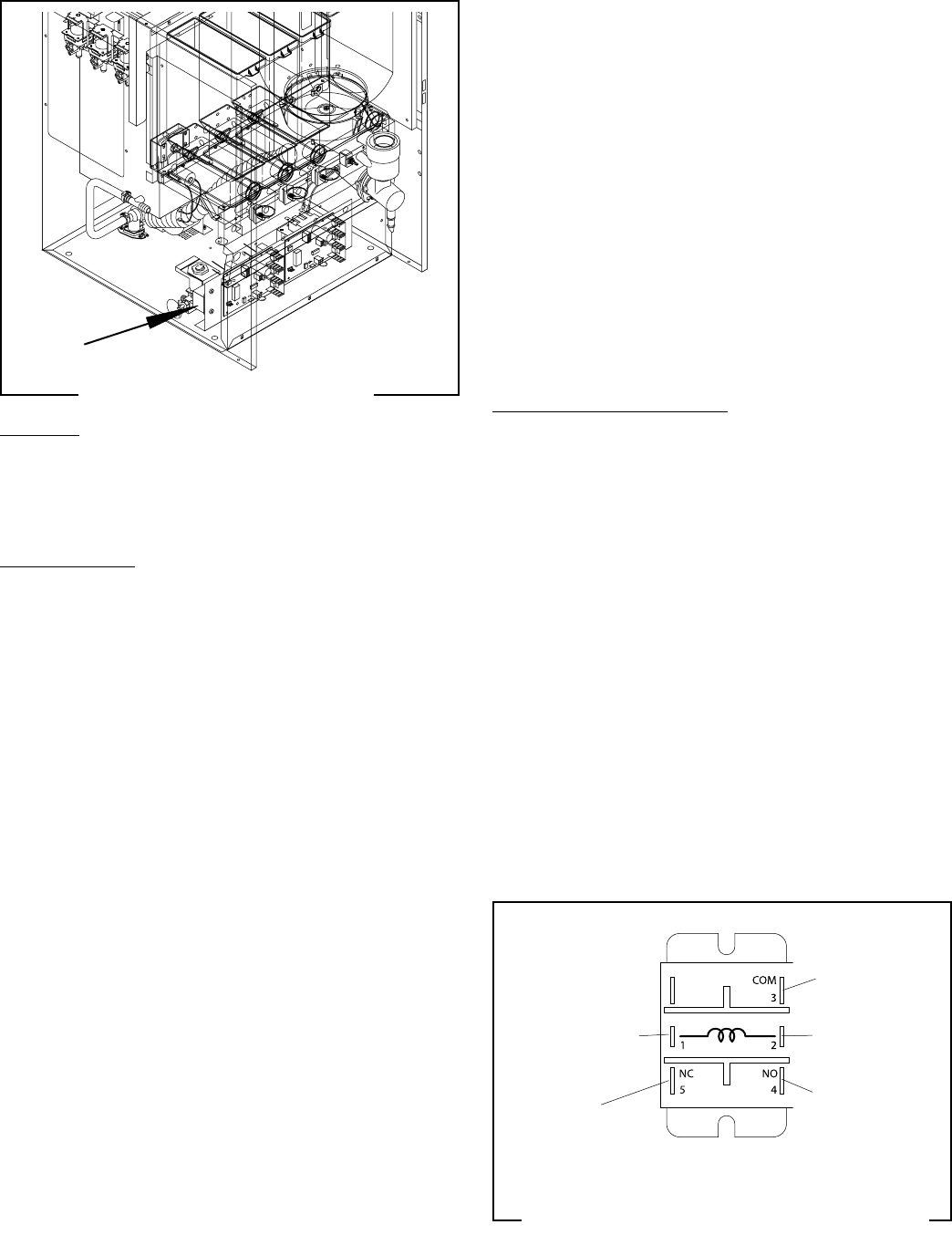
TANK HEATER RELAY (FMD-4,-5,120V Dispensers only)
FIG. 52 TANK HEATER RELAY
P4095
Location:
The tank heater relay is located behind the lower
front access cover, mounted on the left rear side of the
component bracket.
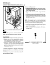
Test Procedure:
1. Disconnect the dispenser from the power source.
2. Place the tank heater switch in the “OFF” (upper)
position.
3. With an ohmmeter, check for continuity between
normally closed (NC-5) and common (COM-3)
terminals of the relay. The indication must be less
than 1 ohm.
If continuity is present as described, proceed to step
4.
If continuity is not present as described, replace the
relay.
4. With an ohmmeter, check the resistance across the
coil terminals (1 & 2) of the relay. The indication
must be approximately 4,000 ohms (4kΩ).
If the resistance measures as described, proceed to
step 5.
If the resistance does not measure as described, replace
the relay.
5. Disconnect the wires from the normally closed (NC-
5) and common (COM-3) terminals of the relay.
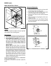
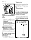
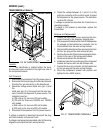
FIG. 53 TANK HEATER RELAY TERMINALS
P2639
SERVICE (cont.)
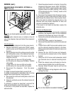
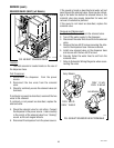
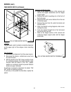
Removal and Replacement:
1. Loosen the three #8-32 screws securing the com-
ponent bracket to the dispenser housing base.
2. Pull component bracket out the front of the dis-
penser far enough so the tank heater relay can be
disconnected from the main wiring harness.
3 Disconnect the tank heater relay from the main
wiring harness.
4. Remove the two #8-32 screws securing the tank
heater relay to the rear of the component bracket.
5. Remove and discard the tank heater relay.
6. Install new tank heater relay on the rear of the
component bracket and secure with two #8-32
screws.
7. Connect the tank heater relay to the main wiring
harness (see Fig. 53).
8. Place the component bracket into position and
tighten the three #8-32 screws.
6. With an ohmmeter, check for continuity between
the normally closed (NC-5) and common (COM-3)
terminals of the relay.
7. Place containers below any three dispense noz-
zles.
8. Connect the dispenser to the power source.
9. Simultaneously initiate dispenses at each of the
selected dispense stations while monitorintg con-
tinuity across the referenced terminals of the tank
heater relay. The indication must be open circuit.
If continuity is absent as described, the relay is func-
tioning correctly.
If continuity is present, replace the relay.
BLK from
Main Harness
BLK from
Main Harness
BRN/BLK from
Main Harness
WHI from
Main Harness
No Connection
42672 122209