


Page 6
ELECTRICAL HOOK-UP
CAUTION – Improper electrical installation will damage electronic components.
1. An electrician must provide electrical service.
2. Determine the available on-site electrical service.
3. Select the desired unit voltage based on the available on-site electrical service.
4. Using a voltmeter, check the voltage and color coding of each conductor at the electrical source.
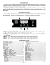
5. Remove the back access panel to gain access to the terminal block.
6. Feed the supply leads through the strain relief at the rear of the brewer.
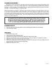
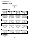
7. Using the above diagrams, connect the desired electrical service to the field wiring terminal block.
8. If wiring the machine for operation on 120/208 or 120/240 volts with a Power Supply Cord, the Power Supply
Cord must be UL Listed Flexible Cord Type SO, SJO, SJTO, HSJO or SJOW, No. 12 AWG, 4 Conductor, Rated
90° C. Attachment Plug Cap must be UL Listed, NEMA 14-20P or L14-20P Configuration, Rated 125/250V,
20 AMPS. If wiring the brewer for operation at 200V or 230V with a Power Supply Cord, the Power Supply
Cord must be of type “H07RN-F” with <HAR> marking, 1.5 mm
2
conductor size, rated mimimom 90°C.
Attachment male plug must be appropriate for Local/National use and must meet any Local/National Regula-
tory requirements/certifications if applicable. The Power Supply Cord must be at least 3 feet (.91 m) long
and maximum 6 feet (1.82 m) long (measured from Strain Relief to end of the Attachment Plug Cap).
NOTE: If the power cord is damaged, it must be replaced by the manufacturer or its service agent or a
similarly qualified person in order to avoid a hazard.
9. Connect the brewer to the power source and verify th
9. Connect the brewer to the power source and verify the voltage at the terminal block.
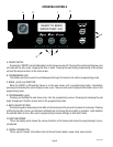
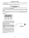
10. Set toggle switch on component bracket to the appropriate position and replace the access panel.
11. If plumbing is to be hooked up later be sure the brewer is disconnected from the power source. If plumbing
has been hooked up, the brewer is ready for Initial Set-Up.
36748 101505
WHITE/VIOLET
BLUE
WHITE
BACK
FRONT
120/208V
120/240V
120V
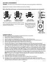
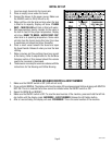
ELECTRICAL REQUIREMENTS
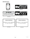
WARNING - The brewer must be disconnected from the power source until specified in Initial Set-Up.
Requirements for brewers without an attached cord set are as follows:
Refer to Data Plate on the Brewer, and local/national electrical codes to determine circuit requirements.
120V AC
single phase models
DUAL VOLT
TOGGLE SWITCH
120/208 & 120/240V AC
single phase models
GREEN GREEN
BLK
RED
120V. A.C.
120V. A.C.
208 or 240V. A.C.
WHI
L1
L2
N
GREEN GREEN
BLK
RED
WHI
L1
L2
N
120V. A.C.
Note: The two electrical services above require 3 current
carring conductors (Neutral, L1 and L2) and a separate
conductor for earth ground
200 or 230V AC
single phase models
Note: This electrical service
consists of 2 current carry-
ing conductors (L1 and L2)
and a separate conductor
for earth ground.
GREEN GREEN
200 or 230V. A.C.
BLK
RED
L1
L2