


19
SERVICE (CONT.)
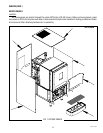
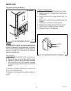
GD Compressor (JDF-2S,4S,4D)
P1684.40
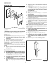
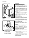
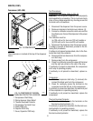
FIG. 11 COMPRESSOR
Location:
The compressor is located at the top of the dispenser
frame.
Test Procedures:
Compressor Start Relay: Refer to FIG. 12
WARNING: The compressor capacitor must be properly
discharged before proceeding. This is most commonly
done on low voltage capacitors by shorting across the
terminals with a screwdriver.
1. Disconnect the dispenser from the power source.
2. Remove compressor terminal cover retainer (4).
3. Connect a voltmeter across the white wire and the
blue/black wire. Connect the dispenser to the power
source.
The indication must be:
(a) 120 volts ac for two wire 120 volt models or
(b) 230 volts ac for two wire 230 volt models.
5. Disconnect the dispenser from the power source.
If voltage is present as described, proceed to the fol-
lowing test procedures.
If voltage is not present as described, refer to the Con-
tactor and check the contactor.
6. Disconnect the two black wires from the compres-
sor start relay.
7. Remove relay from the compressor.
8. Check for continuity across the upper left terminal
and the right pin socket on the rear of the relay.
If continuity is present as described, the compressor
start relay is operating properly.
If continuity is not present as described, replace re-
lay.
Compressor:
1. With the compressor start relay (1) removed, dis-
connect the black wire from the compressor.
2. Check for continuity across the terminal on the
compressor and the left pin on the compressor.
If continuity is present as described, the electrical part
of the compressor is operating properly.
If continuity is not present as described, replace the
compressor.
Thermal Overload Protector:
1. Check for continuity across the terminals on the
thermal overload protector (3).
If continuity is present as described, the thermal over-
load protector is operating properly.
If continuity is not present as described, replace the
thermal overload protector.
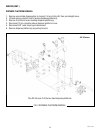
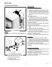
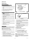
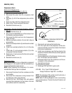
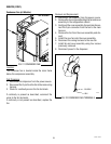
FIG.12 COMPRESSOR THERMAL
OVERLOAD PROTECTOR LOCATION
1. Compressor Start Relay
2. Wiring Harness Strain Relief
3. Thermal Overload Protector
4. Compressor Terminal Cover
2 4
P4040.40
1 3
JDF-4S shown
49179 110613