


44
SERVICE (CONT.)
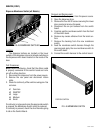
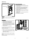
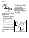
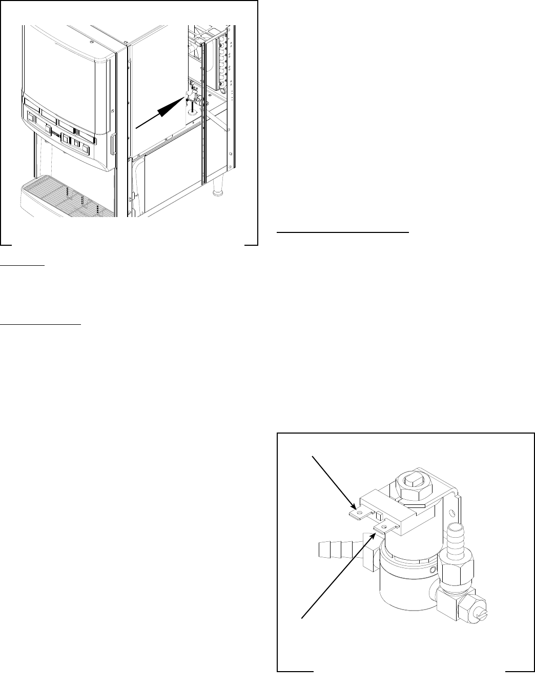
Solenoid - Cold Water (JDF-4S only)
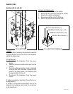
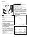
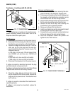
FIG. 62 COLD WATER SOLENOID
TERMINALS
FIG. 61 COLD WATER DISPENSE SOLENOID
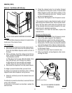
Location:
The Cold Water dispense solenoid is located at the
inside rear of the chassis frame.
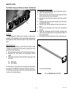
Test Procedures:
1. Disconnect the dispenser from the power source.
2. Disconnect the two wires from the solenoid valve.
Press the Cold Water dispense switch on front of
the door.
3. With a voltmeter, check the voltage across the two
wires. Connect the dispenser to the power source.
The indication must be:
a) 120 volts ac for two wire 120 volt models, three
wire 120/208 volt, and 120/240 volt models.
b) 240 volts ac for two wire 240 volt models.
c) 230 volts ac for two wire 230 volt models.
4. Disconnect the dispenser from the power source.
If voltage is present as described, proceed to #5
If voltage is not present as described, refer to Wiring
Diagrams and check dispenser wiring harness.
5. Check for continuity across the solenoid valve coil
terminals.
If continuity is present as described, reconnect the two
wires to the solenoid.
If continuity is not present as described, replace the
solenoid valve.
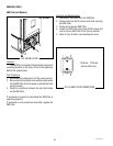
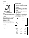
6. Check the solenoid valve for coil action. Connect
the dispenser to the power source. Press the Cold
Water dispense switch and listen carefully in the
vicinity of the solenoid valve for a “clicking” sound
as the coil magnet attracts.
7. Disconnect the dispenser from the power source.
If the sound is heard as described and water will not
pass through the solenoid valve, there may be a block-
age in the tank water outlet before the solenoid valve
or, the solenoid valve may require inspection for wear,
and removal of waterborne particles.
If the sound is not heard as described, replace the
solenoid valve.
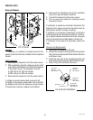
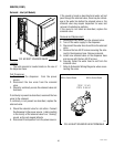
Removal and Replacement:
1. Disconnect the dispenser from the power source.
2. Turn off the water supply to the dispenser.
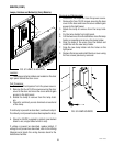
3. Remove the two wires from the solenoid valve.
4. Disconnect the water line from the solenoid valve.
5. Remove the #10-32 screws securing the solenoid
valve to the chassis frame. Remove solenoid valve.
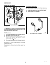
6. Using the #10-32 screws install new solenoid valve
to the chassis frame.
7. Reconnect the water lines to solenoid valve.
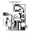
8. Refer to schematic wiring diagrams when recon-
necting the wires.
WHI/VIO to Control Board
WHI to Control Board
49179 110613