


Page 17
SERVICE (cont.)
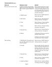
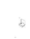
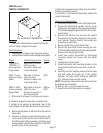
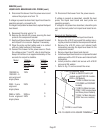
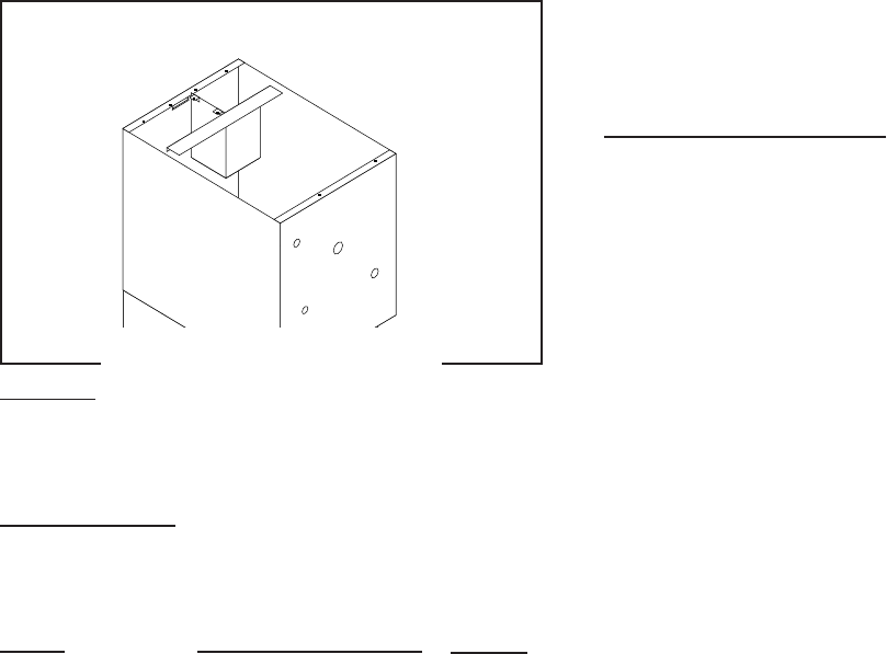
CONTROL THERMOSTAT
FIG. 6 CONTROL THERMOSTAT
P2113.40
Location:
The control thermostat is mounted on the left
front of the top component bracket.
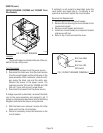
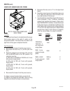
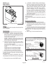
Test Procedures:
1. Disconnect the brewer from the power source.
2. Locate the thermostat and the voltage check points.
Model
120/208V &
120/240V - 3-
wire w/ground
single phase
230V - 2-wire
w/ground single
phase
208V or 240V -
2-wire w/ground
single phase
4. Disconnect the brewer from the power source.
If voltage is present as described, proceed to #5.
If voltage is not present as described, refer to the
wiring diagrams and check the brewer wiring harness.
5. Disconnect the black or red wires from the control
thermostat.
6. Check for continuity across the terminals on the
control thermostat with the control thermostat in
the "ON" position (fully clockwise), continuity must
not be present when the thermostat is in the "OFF"
position (fully counterclockwise).
If continuity is present as described, the control ther-
mostat is operating properly.
If continuity is not present as described, replace the
control thermostat.
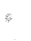
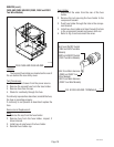
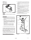
Removal and Replacement:
1. Disconnect the wires from the control thermostat.
2. Remove the thermostat capillary bulb by firmly
pulling up on the capillary at the component bracket.
This will disengage the grommet from the compo-
nent bracket.
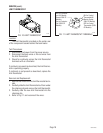
3. Remove the #8-32 screw securing the control
thermostat and mounting bracket to the compo-
nent bracket. Remove control thermostat and
bracket as an assembly.
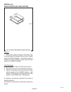
4. Remove knob from control thermostat.
5. Remove the two #6-32 screws securing the con-
trol thermostat to the thermostat mounting bracket.
Remove and discard thermostat.
6. Install new control thermostat on thermostat
mounting bracket and secure with two #6-32
screw.
7. Install knob on thermostat.
8. Install thermostat and mounting bracket on the
component bracket and secure with one #8-32
screw.
9. Carefully bend the capillary tube so that the tube
and bulb inside the brewer are in the vertical
position. The tube should extend an additional
5.5", above the bulb into the brewer.
NOTE: The capillary tube must be clear of any electrical
termination and not kinked.
10. Refer to Fig. 7 and reconnect the wires.
11. Adjust the control thermostat as required.
Check Voltage Across
Black wire on thermo-
stat from main
harness to white wire
in terminal block.
Red wire on thermo-
stat from main
harness to black wire
in terminal block.
Black wire on thermo-
stat from main
harness to red wire in
the terminal block.
Voltage
120V
230V
208V or
240V
10067 040100