


Page 22
10067 040100
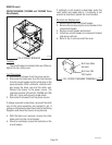
ON/OFF SWITCH
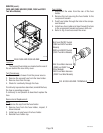
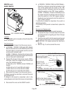
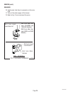
FIG.14 ON/OFF SWITCH
P2053.25
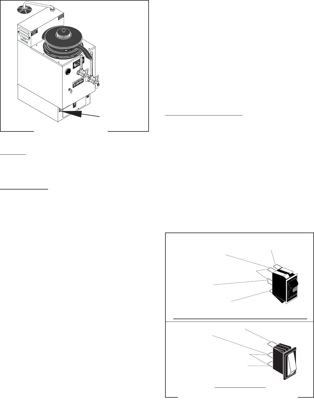
Location:
The ON/OFF switch is located on the left side of the
lower front panel.
Test Procedures:
1. Disconnect the brewer from the power source.
2. a)120/208V, 120/240V, 208V and 240V Models
Remove the black wire on the ON/OFF switch from
the fuse holder or circuit breaker and the red wire
on the switch indicator light.
b) 230V - CE Models - Remove the red wire on the
ON/OFF switch from the fuse holder and the black
wire on the switch indicator light.
3. Connect the brewer to the power source. With a
voltmeter, check the voltage across the removed
wire. The indication must be:
a) 120 volts ac for 120/208 volt and 120/240 volt
models.
b) 208 volts ac for 2-wire 208 volt models.
c) 240 volts ac for 2-wire 240 volt models.
d) 230 volts ac for 2-wire 230 volt models.
4. Disconnect the brewer from the power source.
If voltage is present as described, reconnect the wires
and proceed to #5
If voltage is not present as described, refer to the
wiring diagrams and check the brewer wiring harness.
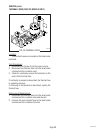
5. Disconnect the wires on the ON/OFF switch.
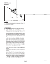
6. a) 120/208V, 120/240V, 208V and 240V Models -
Check for continuity across the terminals on the
rear of the switch with the switch in the "ON"
(upper) position. Continuity must not be present
when the switch is in the "OFF" (lower) position.
b) 230V - CE Models - Check for continuity across
the center terminal (2) and the lower terminal (1)
when the switch is in the "ON" (upper) position.
Continuity must not present when the switch is in
"OFF" (lower) position.
If continuity is present as described, the switch is
operating properly.
If continuity is not present as described, replace the
switch.
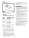
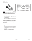
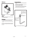
Removal and Replacement:
1. Remove the wires from the switch terminals.
2. Compress the clips on the back side of the switch
mounting bracket and gently push them through
the opening.
3. Push the new switch into the opening and spread
the clips to hold switch in the mounting bracket.
NOTE: ON 230V - CE models terminal (3) must be on
the top.
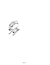
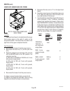
4. Refer to Fig. 15 and reconnect the wires.
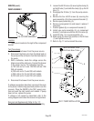
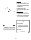
BLK to On/Off Switch
BLK to Liquid Level Board L2
120/208V, 120/240V, 208V and 240V MODELS
BLK from Indicator Light
RED to Fuse
RED to Start Switch, Brew
Timer & Liquid Level Board
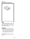
230V - CE Models
P2120.50
FIG. 15 ON/OFF SWITCH TERMINALS
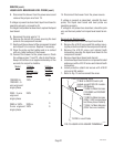
SERVICE (cont.)
BLK to On/Off Switch
BLK to Start Switch
BLK to Circuit
Breaker or Fuse
WHI or RED to Indica-
tor Light
Step #6
Step #6