


Page 21
SERVICE (cont.)
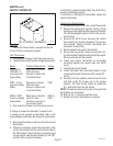
LIQUID LEVEL BOARD AND LEVEL PROBE (cont.)
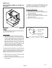
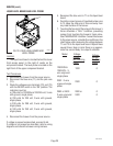
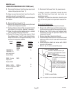
T1 BLU to Solenoid Valve
T2 BLK to ON/OFF Switch (All
models except 230V-CE models-
RED on CE Models)
T3 WHI to Main Harness
(120/208V and120/240V
models)
T3 RED to Main Harness
(208V, 240V single phase
and three phase models)
T3 BLK to Main Harness
(230V two wire models)
T4 PIN to Level Probe
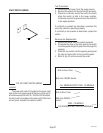
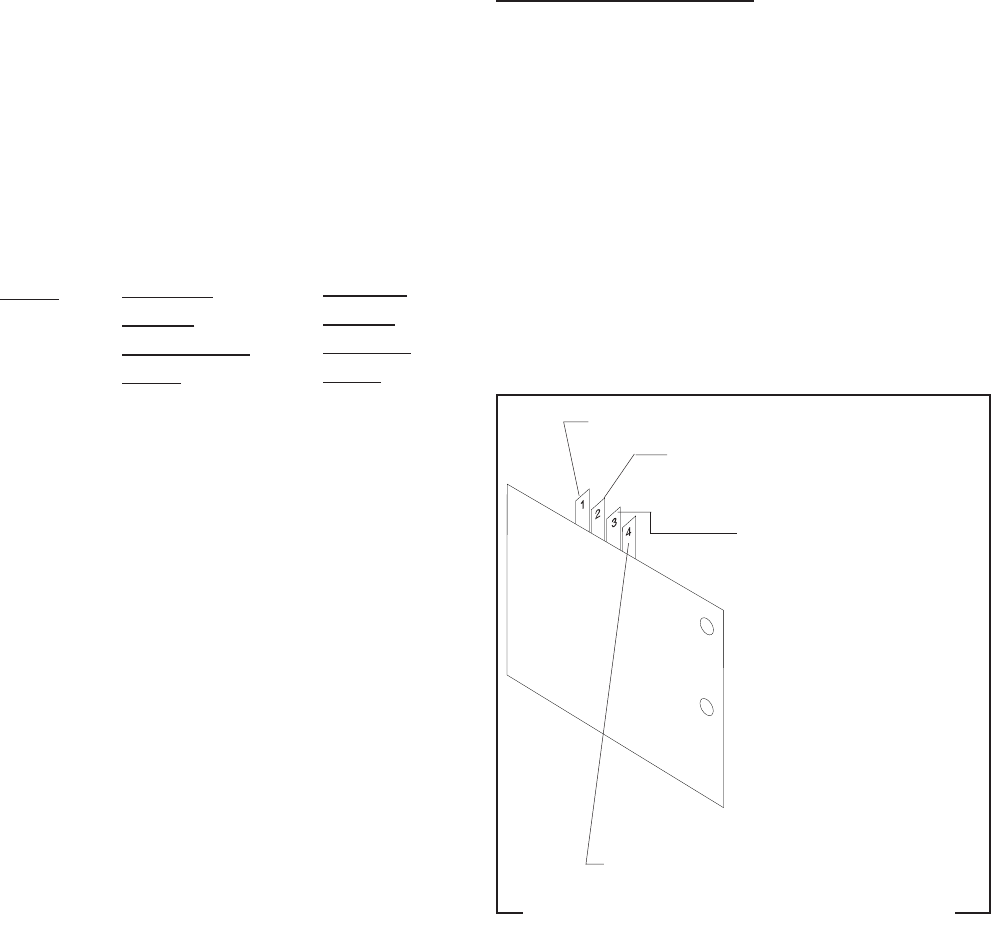
FIG.13 LIQUID LEVEL BOARD TERMINALS
P1733
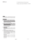
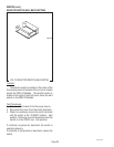
Voltage -
Jumper
Not Touching
Frame
Model
120/208V &
120/240V - 3-
wire w/ground
single phase
230V - 2-wire
w/ground
single phase
208V or 240V -
2-wire w/ground
single phase
Voltage -
Jumper
Touching
Frame
0
0
0
0
10067 040100
14. Disconnect the brewer from the power source.
If voltage is present as described, reinstall the level
probe, the liquid level board and level probe are
operating properly.
If voltage is not present as described, check the pink
wire on the level probe from liquid level board termi-
nal.
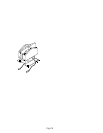
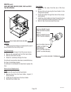
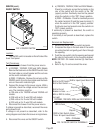
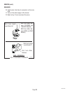
Removal and Replacement:
1. Remove all wires from the liquid level board.
2. Remove the #10-32 screw and flat washer secur-
ing the protective shield to the component bracket.
3. Remove the #10-32 screw and internal tooth
lockwasher securing the liquid level board to the
component bracket.
4. Remove liquid level board and discard.
5. Install new liquid level board on component bracket
and secure with a #10-32 screw and internal tooth
lockwasher.
6. Install protective shield and secure with #10-32
screw and flat washer.
7. Refer to Fig. 13 and reconnect the wires.
8. Disconnect the brewer from the power source and
remove the jumper wire from T4.
If voltage is present as described, liquid level board is
operating properly, proceed to #9.
If voltage is not present as described, replace the liquid
level board.
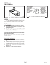
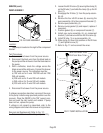
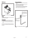
9. Reconnect the pink wire to T4.
10. Remove the two #8-32 screws securing the level
probe to the component bracket.
11. Gently pull the probe out of the component bracket
and inspect for corrosion. Replace if necessary.
12 Place the probe so that neither end is in contact
with any metal surface of the brewer.
13. Connect the brewer to the power source. Check
the voltage across T1 and T3, refer to chart below.
Keep in mind there is an approximate delay of five
seconds for output to stabilize.
120V
230V
208V or
240V