


Page 20
SERVICE (cont.)
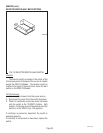
LIQUID LEVEL BOARD AND LEVEL PROBE
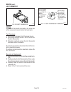
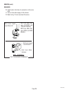
5. Reconnect the blue wire to T1 on the liquid level
board.
6. Carefully connect a piece of insulated jumper wire
to T4. Keep the other end of this wire away from
any metal surface of the brewer.
7. Touching the free end of the jumper to the brewer's
frame simulates a "FULL" condition, preventing
jumper from touching the brewer's frame simu-
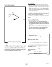
lates "NEED WATER" condition. Connect the brewer
to the power source, simulate the conditions in the
chart below while measuring the voltage between
T1 and T3 0n the liquid level board. Repeat these
several times. Keep in mind there is an approxi-
mate five second delay for output to stabilize.
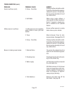
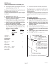
Voltage -
Jumper
Not Touching
Frame
120V
230V
208V or
240V
Model
120/208V &
120/240V - 3-
wire w/ground
single phase
230V - 2-wire
w/ground single
phase
208V or 240V -
2-wire w/ground
single phase
Voltage -
Jumper
Touching
Frame
0
0
0
0
10067 040100
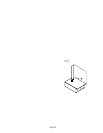
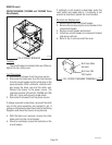
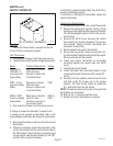
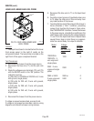
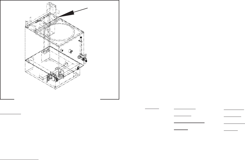
FIG.12 LIQUID LEVEL BOARD AND
LEVEL PROBE
P2208.40
Location:
The liquid level board is located behind the lower
front access panel, to the right of center on the
component bracket. The level probe is located on the
right front of the upper component bracket.
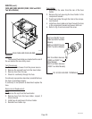
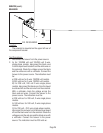
Test Procedures:
1. Disconnect the brewer from the power source.
2. Disconnect the blue wire (T1) and the pink wire
(T4).
3. Check the voltage across terminals (T2) and (T3)
with the ON/OFF switch in the "ON" position. The
indication must be:
a) 120 volts for 120/208 and 120/240 volt, 3-wire
with ground, single phase;
b) 230 volts for 230 volt, 2-wire with ground,
single phase;
c) 208 volts for 208 volt, 2-wire with ground,
single phase;
d) 240 volts for 240 volt, 2-wire with ground,
single phase.
4. Disconnect the brewer from the power source.
If voltage is present as described, proceed to #5.
If voltage is not present as described, refer to wiring
diagrams and check the brewer wiring harness.