


Page 13
P2178.60
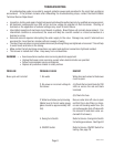
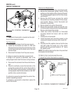
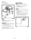
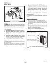
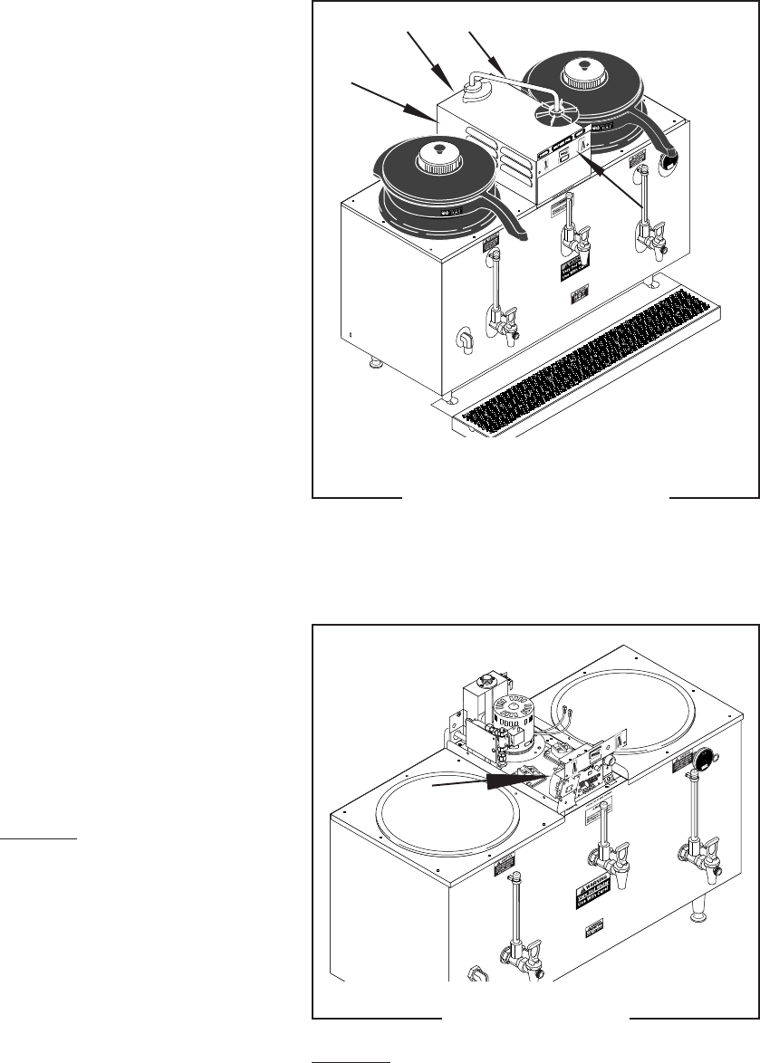
FIG. 2 CONTACTOR
Location:
The contactor is located on the left front of the
component bracket
SERVICE
This section provides procedures for testing and
replacing various major components used in this
brewer should service become necessary. Refer to
Troubleshooting
for assistance in determining the
cause of any problem.
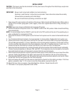
WARNING - Inspection, testing, and repair of elec-
trical equipment should be performed only by quali-
fied service personnel. The brewer should be un-
plugged when servicing, except when electrical tests
are required and the test procedure specifically states
to plug in the brewer.
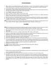
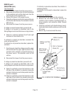
COMPONENT ACCESS
WARNING - Disconnect the brewer from the power
source before the removal of any panel or the replace-
ment of any component.
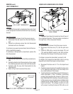
All components are accessible by the removal of
the swing spout, front cupola cover, rear cupola cover
and the cupola.
Disconnect the swing spout nut from the swing
spout base fitting. Remove swing spout.
Remove the four #8-32 screws, two on the front
and rear, securing front and rear cupola covers to the
cupola.
Slip cupola off of the component bracket.
FIG. 1 COMPONENT ACCESS
P2104.25
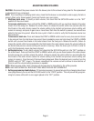
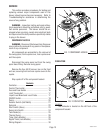
Contents
Contactor ............................................................. 14
Control Thermostat.............................................. 15
Fuse and Fuse Holder .......................................... 16
Limit Thermostat ................................................. 17
Liquid Level Board and Level Probe.................... 17
ON/OFF Switch..................................................... 19
Pump ................................................................... 20
Selector Switch (Half Batch) ................................ 21
Solenoid .............................................................. 22
Start Switch (Brew) ............................................. 23
Swing Arm Switch ............................................... 24
Tank Heater(s) ..................................................... 25
Thermal Fuses .................................................... 26
Timer (Early Models) ........................................... 26
Digital Timer (Late Models) ................................. 28
Wiring Diagram ................................................... 30
CONTACTOR
10060.3 070102