


Page 14
SERVICE (cont.)
Test Procedures:
1. Disconnect the brewer from the power source.
2. Disconnect the red wire from the limit thermostat
to the contactor coil and the black wire from the
main harness to the contactor coil.
3. Connect the brewer to the power source.
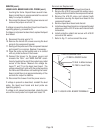
4. Check the voltage across the limit wire and the wire
from the the main harness.The indication must be
230 volts ac.
5. Disconnect the brewer from the power source.
If voltage is present as described, proceed to #6.
If voltage is not present as described refer to the
Wiring Diagram and check the brewer wiring harness.
6. Check for continuity between the left and right
terminals on the contactor coil.
If continuity is present as described, reconnect the
wires and proceed to #7.
If continuity is not present as described, replace the
contactor.
7. On all brewers check the voltage across the upper
left terminal and the upper right terminal on the
contactor with a voltmeter. Connect the brewer to
the power source. The indication must be 230
volts ac.
8. Disconnect the brewer from the power source.
If voltage is present as described, proceed to #9.
If voltage is not present as described, refer to the
wiring diagrams and check the brewer wiring harness.
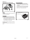
9. Check for continuity across the terminals on the
left side of the contactor by manually closing the
contacts. Continuity must not be present when the
contact is released.
10. Check for continuity across the terminals on the
right side of the contactor by manually closing the
contacts.Continuity must not be present when the
contact is released.
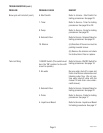
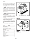
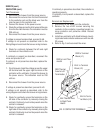
CONTACTOR (cont.)
BLK to Terminal
Block (L2)
If continuity is present as described, the contactor is
operating properly.
If continuity is not present as described, replace the
contactor.
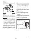
Removal and Replacement:
1. Disconnect all the wires from the contactor.
2. Remove the two #8-32 screws securing the
contactor to the contactor mounting bracket, re-
move contactor and protective shield. Discard
contactor.
3. Install new contactor with shield between mount-
ing bracket and contactor and secure with two #8-
32 screws
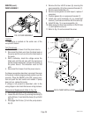
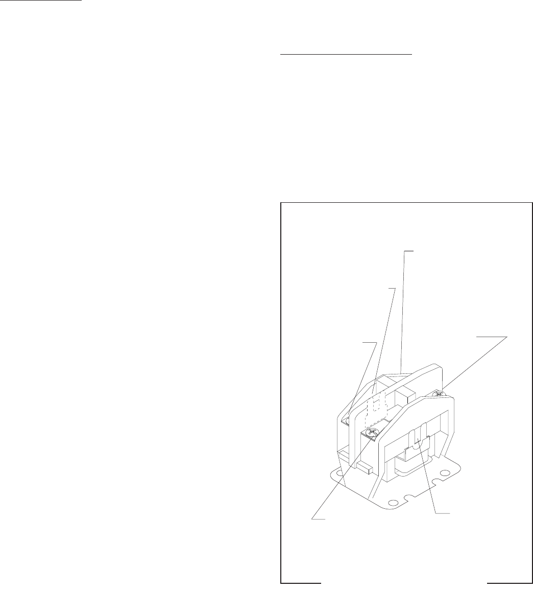
4. Refer to Fig. 3 and reconnect the wires.
RED Thermal
Fuse to Left
Tank Heater
BLK to Termi-
nal Block (L2)
RED to Limit Ther-
mostat
BLK Thermal Fuse
to Right Tank
Heater
RED to Terminal
Block (L1)
P2107.50
FIG. 3 CONTACTOR TERMINALS
10060.3 070102