


Page 15
SERVICE (cont.)
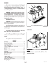
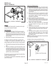
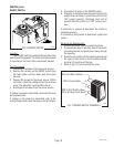
CONTROL THERMOSTAT
FIG. 4 CONTROL THERMOSTAT
P2178.60
Location:
The control thermostat is mounted on the right
front of the component bracket.
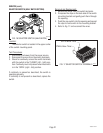
Test Procedures:
1. Disconnect the brewer from the power source.
2. Locate the thermostat and check for 230 volts
between the red wire from the main harness on the
control thermostat and the black wire on the main
terminal block
3. Disconnect the brewer from the power source.
If voltage is present as described, proceed to #4.
If voltage is not present as described, refer to the
wiring diagram and check the brewer wiring harness.
4. Disconnect the red wires from the control thermo-
stat.
5. Check for continuity across the terminals on the
control thermostat with the control thermostat in
the "ON" position (fully clockwise), continuity must
not be present when the thermostat is in the "OFF"
position (fully counterclockwise).
If continuity is present as described, the control ther-
mostat is operating properly.
If continuity is not present as described, replace the
control thermostat.
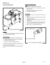
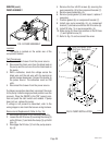
Removal and Replacement:
1. Disconnect the wires from the control thermostat.
2. Remove the thermostat capillary bulb by firmly
pulling up on the capillary at the component bracket.
This will disengage the grommet from the compo-
nent bracket.
3. Remove the #8-32 screw securing the control
thermostat and mounting bracket to the compo-
nent bracket. Remove control thermostat and
bracket as an assembly.
4. Remove knob from control thermostat.
5. Remove the two #6-32 screws securing the con-
trol thermostat to the thermostat mounting bracket.
Remove and discard thermostat.
6. Install new control thermostat on thermostat
mounting bracket and secure with two #6-32
screws.
7. Install knob on thermostat.
8. Install thermostat and mounting bracket on the
component bracket and secure with one #8-32
screw.
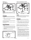
9. Carefully bend the capillary tube so that the tube
and bulb inside the brewer are in the vertical
position with the grommet located 5 1/2 " above
the capillary bulb.
NOTE: The capillary tube must be clear of any electrical
termination and not kinked.
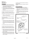
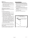
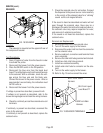
10. Refer to Fig. 5 and reconnect the wires.
11. Adjust the control thermostat as required.
RED from Main
Harness
RED to Limit Thermostat
FIG. 5 CONTROL THERMOSTAT TERMINALS
P1730
10060.3 070102