


Page 27
SERVICE (cont.)
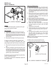
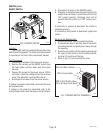
TIMER (Early Models)OLD STYLE(cont.)
If voltage is present as described, proceed to #8.
If voltage is not present as described, refer to the
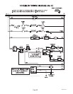
wiring diagram and check the brewer wiring harness.
8. Disconnect the black and white wires to the swing
arm switch and pump leads.
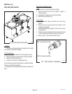
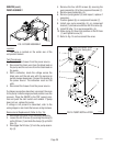
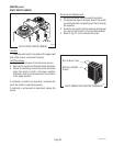
9. With a voltmeter, check the voltage across the
black and white wires when the "ON/OFF" switch is
in the "ON" (upper) position and the start switch
pressed to the start position and released. Connect
the brewer to the power source. The indication
must be 230 volts ac.
If voltage is present as described, the brew timer is
operating properly. To obtain the desired brew vol-
ume, reset the timer dial as required.
If voltage is not present as described, replace the
timer.
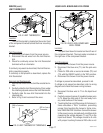
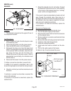
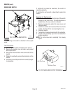
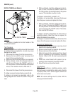
Removal and Replacement:
1. Separate all connectors between the brewer wir-
ing harness and the timer.
2. Disconnect the timer leads from the swing arm
switch lead and pump leads.
3. Remove the two #8-32 screws securing the brew
timer to the component bracket and remove timer.
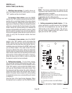
4. Install new timer circuit board as described in
Late
Model Timer
section on the following pages.
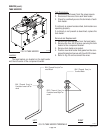
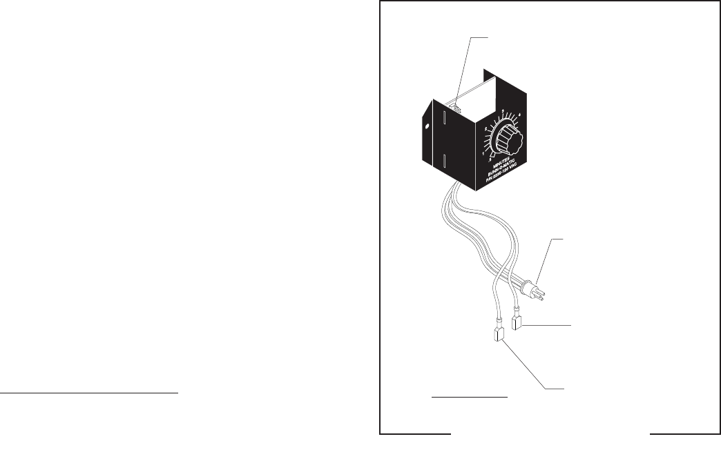
5. Refer to Fig. 30 to reconnect the wires.
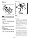
6. Install the Timer Setting Decal, provided with the
timer replacement kit, on the back of the front
access panel.
7. Adjust the timer as required. Refer to
Late Model
Timer
section on the following pages.
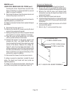
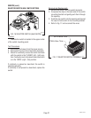
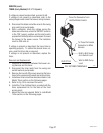
To Three Pin Female
Connector on Main
Harness
BLK to BLK Swing
Arm Switch Lead
WHI to RED Pump
Lead
Three Pin Connector from
Half/Full Batch Switch
FIG. 28 TIMER TERMINALS
P1751
OLD STYLE
10060.3 070102