


Page 20
SERVICE (cont.)
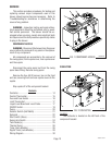
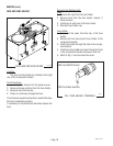
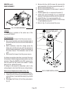
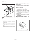
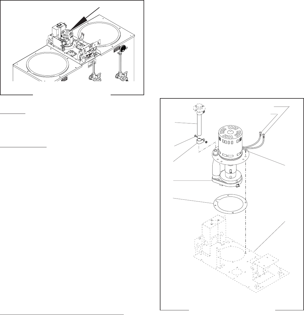
PUMP ASSEMBLY
FIG.14 PUMP ASSEMBLY
P2178.55
Location:
The pump is located on the center rear of the
component bracket.
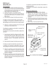
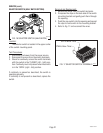
Test Procedures:
1. Disconnect the brewer from the power source.
2. Disconnect the black wire from the black lead on
the pump and the red wire from the black lead on
the pump.
3. With a voltmeter, check the voltage across the
black wire and the red wire with the swing arm
switch plunger depressed. Connect the brewer to
the power source. The indication must be 230
volts.
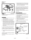
4. Disconnect the brewer from the power source.
If voltage is present as described, reconnect the wires
to the pump. Install swing spout and position over the
reservoir. Place the ON/OFF in the "ON" (upper) posi-
tion and push the start switch and release. If pump
does not run, replace the pump.
If voltage is not present as described, refer to the
wiring diagram and check the brewer wiring harness.
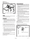
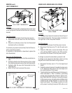
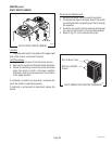
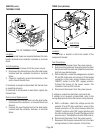
Removal and Replacement (Refer to Fig. 15):
1. Disconnect the wires from the pump assembly.
2. Loosen the #8-32 screw (2) securing the clamp (3)
on the fill tube (1) and slide the clamp (3) up the fill
tube (1).
3. Disengage the fill tube (1) from the pump assem-
bly (4).
4. Remove the four #8-32 screws (6) securing the
pump assembly (4) to the component bracket (7).
5. Remove pump assembly (4).
6. Remove pump gasket (5) and inspect, replace if
necessary.
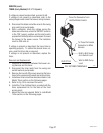
7. Position gasket (5) on component bracket (7).
8. Install new pump assembly (4) on component
bracket (7) and secure with four #8-32 screws (6).
9. Install fill tube (1) on pump assembly (4).
10. Slide clamp (3) down into position on the fill tube
(1) and tighten screw (2).
11. Refer to Fig. 15 and reconnect the wires.
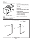
RED from Brew Timer
BLK from Swing Arm
Switch
1
2
3
4
5
6
7
FIG.15 PUMP INSTALLATION
P1737.55
10060.3 070102