


Page 22
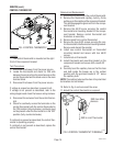
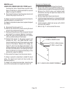
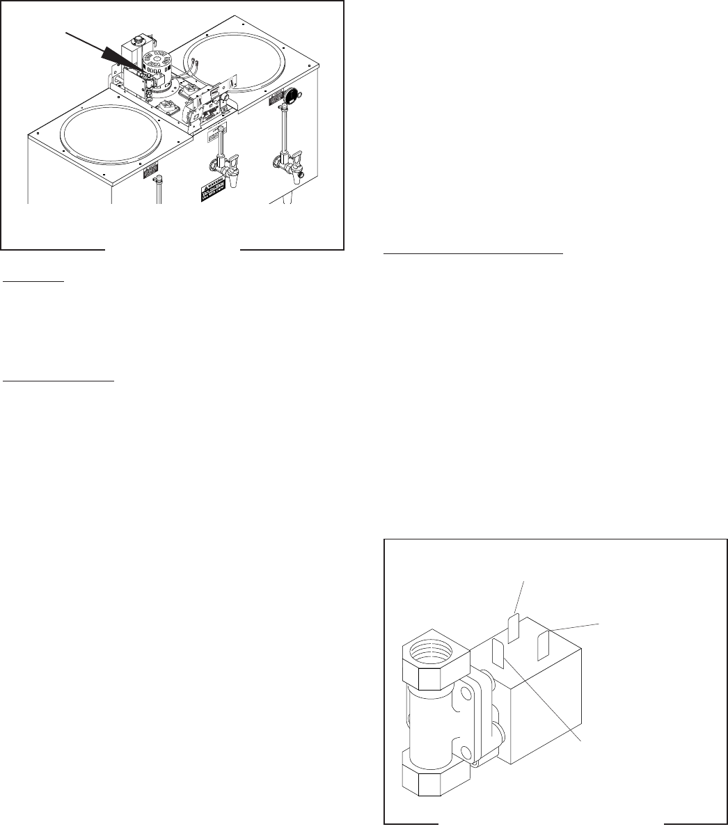
BLU from Liquid
Level Board T1
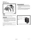
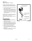
FIG. 19 SOLENOID TERMINALS
P2110.50
SERVICE (cont.)
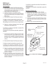
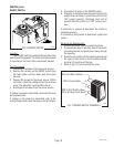
SOLENOID
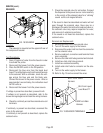
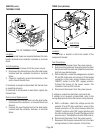
FIG. 18 SOLENOID
P2178.55
Location:
The solenoid is mounted on the upper left rear of
the component bracket.
Test Procedures:
1. Drain 1/2 gallon of water from the faucet in order
to activate the probe.
2. Disconnect the brewer from the power source.
3. Place the ON/OFF switch in the ON position.
4. Disconnect the blue wire from the liquid level
board T1 and the black wire from the main harness
to the solenoid. With a voltmeter, check the volt-
age across the blue wire and the black wire.
Connect the brewer to the power source. After an
approximate 5 second delay, the indication must
be 230 volts ac.
5. Disconnect the brewer from the power source.
If voltage is present as described, proceed to #6.
If voltage is not present as described, refer to the
brewer wiring diagram and check the wiring harness.
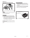
6. Check for continuity across the solenoid valve coil
terminals.
If continuity is present as described, reconnect the
wires to the solenoid.
If continuity is not present as described, replace the
solenoid valve.
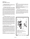
7. Check the solenoid valve for coil action. Connect
the dispenser to the power source. Listen carefully
in the vicinity of the solenoid valve for a "clicking"
sound as the coil magnet attracts.
If the sound is heard as described and water will not
pass through the solenoid valve, there may be a
blockage in the water line before the solenoid valve or,
the solenoid valve may require inspection for wear,
and removal of waterborne particles.
If the sound is not heard as described, replace the
solenoid valve.
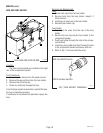
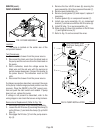
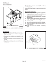
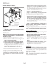
Removal and Replacement:
1. Remove all wires from the solenoid valve.
2. Turn off the water supply to the brewer.
3. Disconnect the water inlet line from the connector
on the solenoid valve.
4. Remove solenoid, connectors and tank inlet tube
as an assembly.
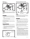
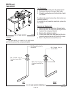
5. Remove the tank inlet tube grommet and discard.
6. Install new tank inlet tube grommet.
7. Install new solenoid assembly.
8. Install water inlet tube to connector on the sole-
noid.
9. Turn on the water supply to the brewer.
10. Refer to Fig. 19 and reconnect the wires.
BLK from Main
Harness
GRN from Main
Harness
10060.3 070102