


Page 17
LIMIT THERMOSTAT
SERVICE (cont.)
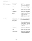
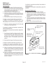
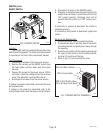
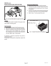
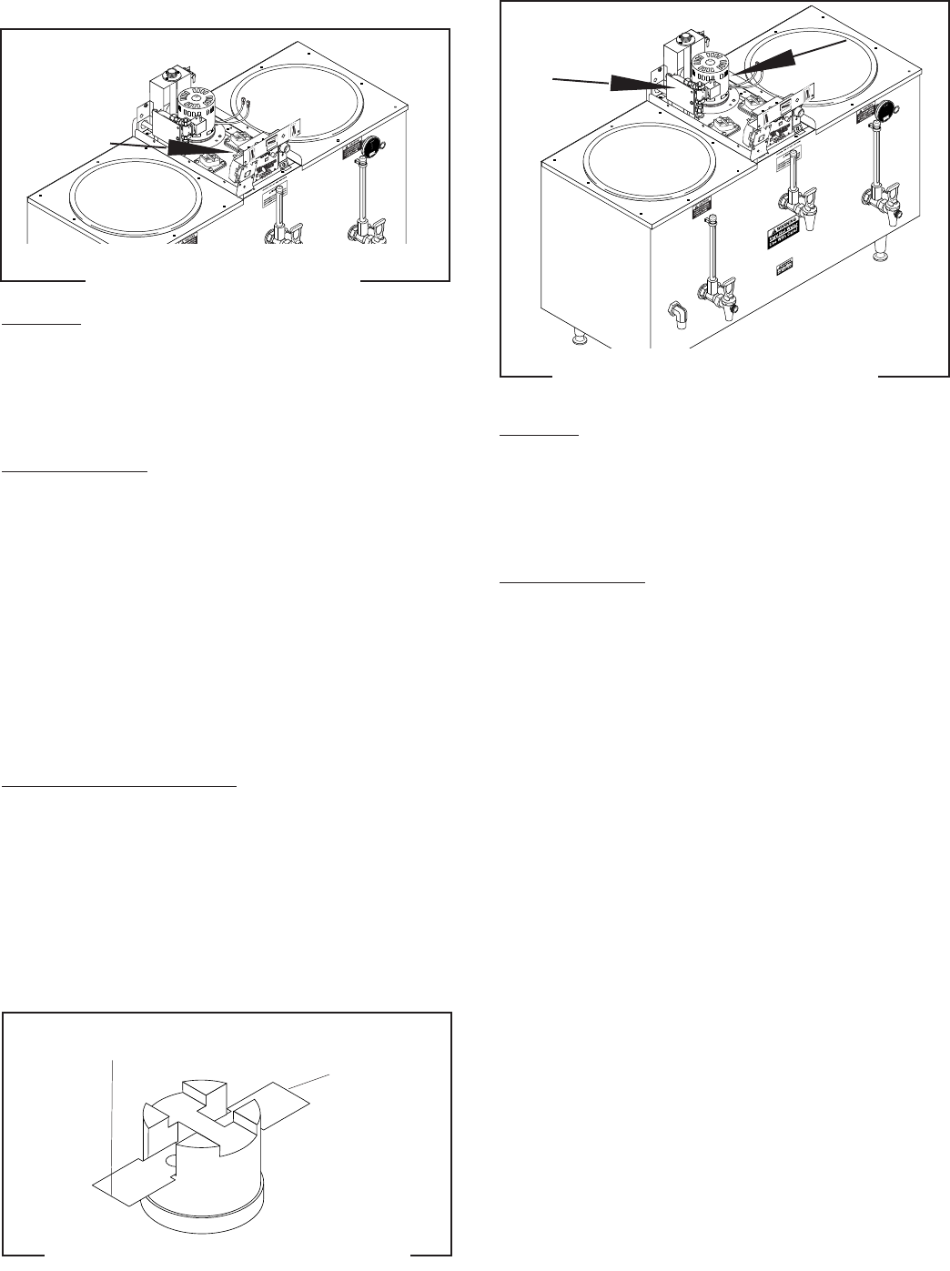
FIG. 9 LIMIT THERMOSTAT TERMINALS
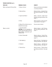
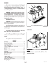
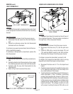
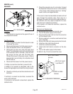
FIG. 8 LIMIT THERMOSTAT
P2178.55
Location:
The limit thermostat is located on the center front
of the component bracket behind the timer mounting
bracket.
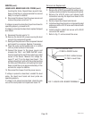
Test Procedures:
1. Disconnect the brewer from the power source.
2. Disconnect the red wires from the limit thermo-
stat.
3. Check for continuity across the limit thermostat
terminals with an ohmmeter.
If continuity is present as described, the limit thermo-
stat is operating properly.
If continuity is not present as described, replace the
limit thermostat.
Removal and Replacement:
1. Remove the wires from the limit thermostat termi-
nals.
2. Carefully slide the limit thermostat out from under
the retaining clip and remove the limit thermostat.
3. Carefully slide the new limit thermostat into the
retaining clip.
4. Refer to Fig. 9 and reconnect the wires.
RED to Control
Thermostat
RED to Contactor
Coil
LIQUID LEVEL BOARD AND LEVEL PROBE
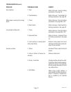
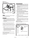
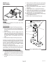
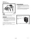
FIG.10 LIQUID LEVEL BOARD AND
LEVEL PROBE
P2178.55
Location:
The liquid level board is located on the left rear of
the component bracket. The level probe is located on
the right rear of the component bracket.
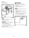
Test Procedures:
1. Disconnect the brewer from the power source.
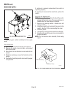
2. Disconnect the blue wire (T1) and the pink wire
(T4).
3. Check for 230 volts ac across terminals (T2) and
(T3) with the ON/OFF switch in the "ON" position.
4. Disconnect the brewer from the power source.
If voltage is present as described, proceed to #5.
If voltage is not present as described, refer to wiring
diagram and check the brewer wiring harness.
5. Reconnect the blue wire to T1 on the liquid level
board.
6. Carefully connect a piece of insulated jumper wire
to T4. Keep the other end of this wire away from
any metal surface of the brewer.
7. Touching the free end of the jumper to the brewer's
frame simulates a "FULL" condition, preventing
jumper from touching the brewer's frame simu-
lates "NEED WATER" condition. Connect the brewer
to the power source, simulate each condition while
measuring the voltage between T1 and T3 on the
liquid level board. The voltage should be 0 volts
with jumper touching frame and 230 volts ac not
10060.3 070102