


Page 18
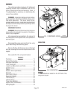
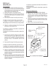
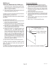
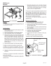
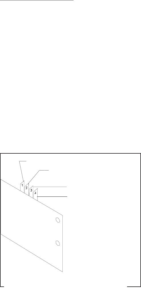
T1 BLU to Solenoid Valve
T2 RED to ON/OFF Switch
T3 BLK to Main Harness
T4 PNK to Level Probe
FIG.11 LIQUID LEVEL BOARD TERMINALS
P1733.50
SERVICE (cont.)
LIQUID LEVEL BOARD AND LEVEL PROBE (cont.)
touching the frame. Repeat these several times.
Keep in mind there is an approximate five second
delay for output to stabilize.
8. Disconnect the brewer from the power source and
remove the jumper wire from T4.
If voltage is present as described, liquid level board is
operating properly, proceed to #9.
If voltage is not present as described, replace the liquid
level board.
9. Reconnect the pink wire to T4.
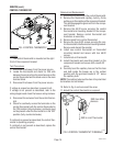
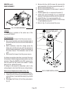
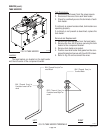
10. Remove the two #8-32 screws securing the level
probe to the component bracket.
11. Gently pull the probe out of the component bracket
and inspect for corrosion. Replace if necessary.
12 Place the probe so that neither end is in contact
with any metal surface of the brewer.
13. Connect the brewer to the power source and
simulate the "FULL" and "NEED WATER" condi-
tions by touching the end of the probe to any metal
surace of the brewer. Measure the voltage be-
tween T1 and T3 on the liquid level board. The
voltage should be 0 volts with the probe touching
the frame and 230 volts ac not touching the frame.
Keep in mind there is an approximate delay of five
seconds for output to stabilize.
14. Disconnect the brewer from the power source.
If voltage is present as described, reinstall the level
probe, the liquid level board and level probe are
operating properly.
If voltage is not present as described, check the pink
wire on the level probe from liquid level board T4.
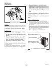
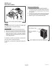
Removal and Replacement:
1. Remove all wires from the liquid level board.
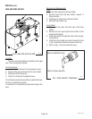
2. Remove the #10-32 screw and flat washer secur-
ing the protective shield to the component bracket.
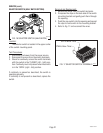
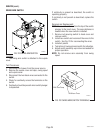
3. Remove the #10-32 screw and internal tooth
lockwasher securing the liquid level board to the
component bracket.
4. Remove liquid level board and discard.
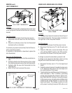
5. Install new liquid level board on component bracket
and secure with a #10-32 screw and internal tooth
lockwasher.
6. Install protective shield and secure with #10-32
screw and flat washer.
7. Refer to Fig. 11 and reconnect the wires.
10060.3 070102