


38
SERVICE (cont.)
COMPRESSOR (APPLIANCES) (ULTRA-1)
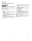
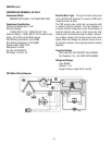
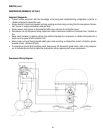
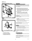
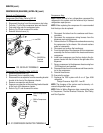
FIG. 24 COMPRESSOR &
COMPONENT LOCATIONS
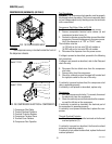
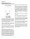
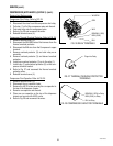
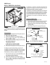
FIG. 25 COMPRESSOR THERMAL
OVERLOAD PROTECTOR LOCATION
Test Procedures:
Compressor Start Relay: Refer to FIG. 25
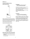
WARNING: The compressor capacitor must be properly
discharged before proceeding. This is most commonly done
on low voltage capacitors by shorting across the terminals
with a screwdriver.
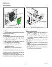
1. Disconnect the dispenser from the power source.
2. Remove compressor terminal cover retainer (4).
3. Connect a voltmeter across the white wire and the white/
orange wire. Connect the dispenser to the power source.
Verify the dispenser is in “ICE” or “CHILL” mode.
The indication must be:
(a) 120 volts ac for two wire 120 volt models or
(b) 230 volts ac for two wire 230 volt models.
5. Disconnect the dispenser from the power source.
If voltage is present as described, proceed to the following
test procedures.
If voltage is not present as described, refer to the Contactor
and check the contactor.
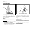
6. Disconnect the two black wires from the compressor
start relay.
7. Remove relay from the compressor.
8. Check for continuity across the upper left terminal and
the right pin socket on the rear of the relay.
If continuity is present as described, the compressor start
relay is operating properly.
If continuity is not present as described, replace relay.
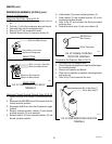
Compressor:
1. With the compressor start relay (1) removed, disconnect
the black wire from the compressor.
2. Check for continuity across the terminal on the compres-
sor and the left pin on the compressor.
If continuity is present as described, the electrical part of
the compressor is operating properly.
If continuity is not present as described, replace the com-
pressor.
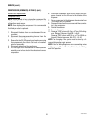
Thermal Overload Protector:
1. Check for continuity across the terminals on the thermal
overload protector (3).
If continuity is present as described, the thermal overload
protector is operating properly.
If continuity is not present as described, replace the thermal
overload protector.
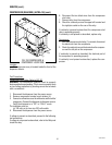
Location:
The compressor assy is located inside the front of the
dispenser chassis.
2 4
1. Compressor Start Relay
2. Compressor Run Capacitor
3. Thermal Overload Protector
4. Compressor Terminal Cover
3 1
41084 102709