


50
SERVICE (cont.)
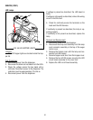
LAMP CORD CONNECTOR
If continuity is not present when lamp cord assembly
is connected or continuity is present when lamp cord
assembly is not connected, replace the lamp cord
connector.
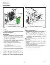
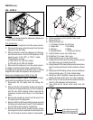
Removal and Replacement:
1. Disconnect the lamp cord assembly from the lamp
cord connector.
2. Remove the two #8-32 locking screws securing the
auger motor cover the auger motor bracket/cooling
drum bracket. Move cover back far enough to gain
access to the lamp cord connector.
3. Disconnect the lamp cord connector wires from
the dispenser main wiring harness.
4. Remove nut and washer securing the lamp cord
connector to the auger motor cover and discard
nut, washer and lamp cord connector.
5. Remove new nut and washer from new lamp cord
connector.
6. Push new lamp cord connector through the hole
in the auger motor cover and secure with the new
nut and washer.
7. Reconnect the wires on the cord connector to the
dispenser main wiring harness.
8. Position auger motor cover on auger motor bracket/
cooling drum bracket and secure with two #8-32
locking screws.
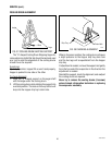
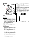
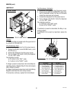
9. Refer to Fig. 48 when reconnecting wires.
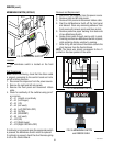
FIG.48 LAMP CORD CONNECTOR
P1323
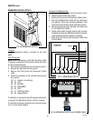
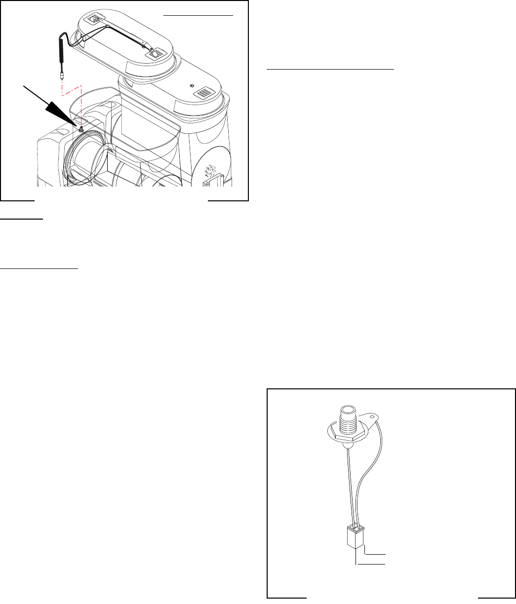
FIG. 47 LAMP CORD CONNECTOR
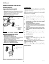
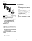
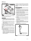
Location:
The lamp cord connectors are located inside the
center top of the auger motor covers.
Test Procedures:
1. Disconnect the dispenser from the power source.
2. Disconnect the plug on the dispenser main harness
from the connector from the lamp cord connec-
tor.
3. Connect the dispenser to the power source. Turnon
power (I/O) switch. The indication must be approxi-
mately 12.6 volts dc.
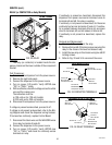
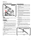
4. Disconnect the dispenser from the power source.
If voltage is present as described, proceed to #5.
If voltage is not present as described, refer to the
Wiring Diagram and check the dispenser main wiring
harness.
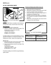
NOTE: Lamp cord assembly (Fig. 47) and lamps, must
be tested and determined to be functioning properly
before proceeding to step 5.
5. Check for continuity across the black wire pin and
red wire pin of the lamp cord connector (Fig. 48).
Continuity must be present when the lamp cord
assembly is connected and must not be present
when lamp cord assembly is disconnected from
lamp cord connector.
BLK to Main Wiring Harness
RED to Main Wiring Harness
ULTRA-2 shown
41084 102709