57
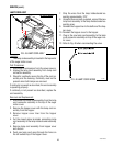
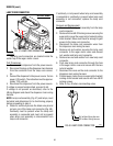
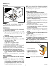
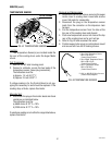
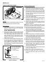
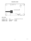
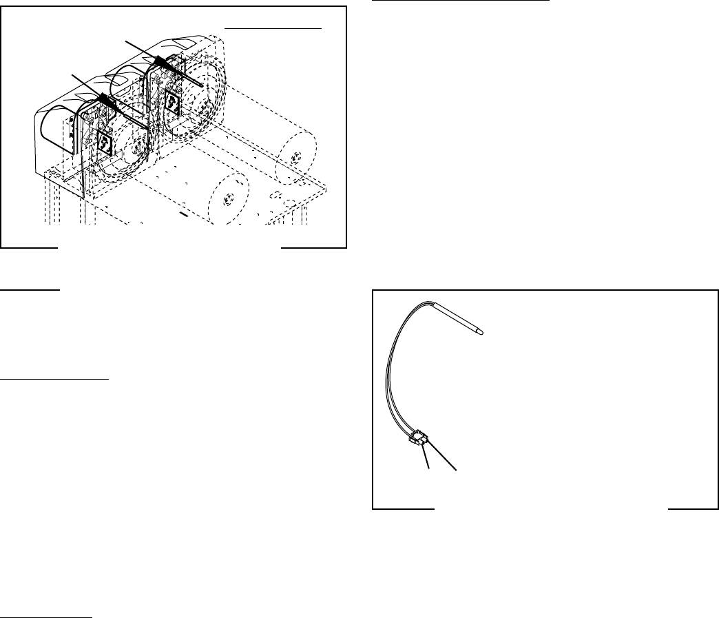
FIG. 62 TEMPERATURE SENSOR
SERVICE (cont.)
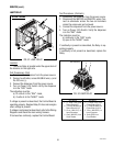
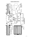
TEMPERATURE SENSOR
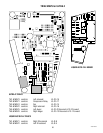
FIG. 61 TEMPERATURE SENSOR
P1341
Location:
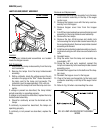
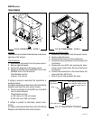
The Temperature Sensor(s) are located inside the
top rear of the cooling drum under the Auger Motor
covers.
Test Procedures:
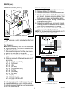
1. Remove the left side housing panel.
2. Connect a voltmeter, across the two leads of the
temperature sensor (leave plug connected);
The indication must be:
a) Approx. 1.4 vdc @ 71° F
b) Approx. 2.6 vdc @ 32° F
If voltage reading is 0v, the Control Board is not sup-
plying the necessary 5v and should be replaced. If the
reading stays at 5vdc, replace thermistor.
Alternate Test:
2. Disconnect the plug on thermistor leads and check
resistance as indicated below.
The indication must be:
a) 5650 ohms @ 32° F ± 10%
b) 2000 ohms @ 77° F ± 10%
If resistance reading is not within the range listed above,
replace thermistor.
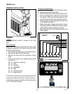
Removal and Replacement:
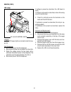
1. Remove the two #8-32 screws securing the auger
motor cover to cooling drum mount and remove
cover. Set aside for reassembly.
2. Disconnect the plug on the temperature sensor
leads from the connector on the dispenser main
harness.
3. Pull the temperature sensor from the tube at the
top rear of the cooling drum and discard.
4. Push new temperature sensor into tube at the top
rear of the cooling drum as far as it will go.
5. Refer to Fig. 62 and reconnect the wires.
6. Position auger motor cover on cooling drum mount
and secure with two #8-32 locking screws.
ULTRA-2 shown
1. Ultra-2 Left Temperature Sensor
WHI to TAN J13-21
(Control Board) Positive
1. Ultra-2 Right Temperature Sensor
WHI to PNK J13-22
(Control Board) Positive
1. Ultra-1 Temperature Sensor
WHI to TAN J10-3
(Control Board) Positive
2. WHI to WHI/BLK Main Harness
(Control Board) Negative
2 1
41084 102709


